How to Build a Tiny Drawing Robot at Maker Faire Bay Area 2016

Drawing Robots at Maker Faire 2016!

Drawing Robots at Maker Faire 2016!

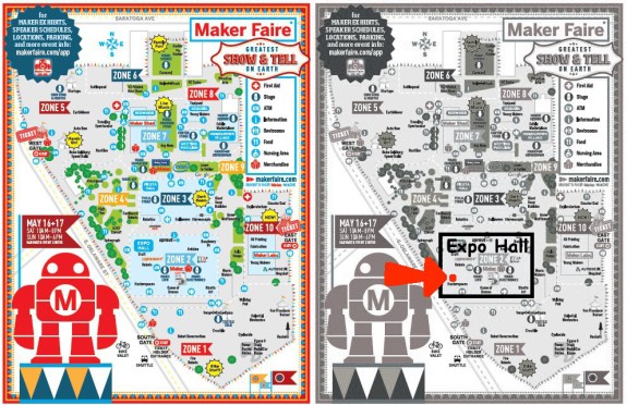
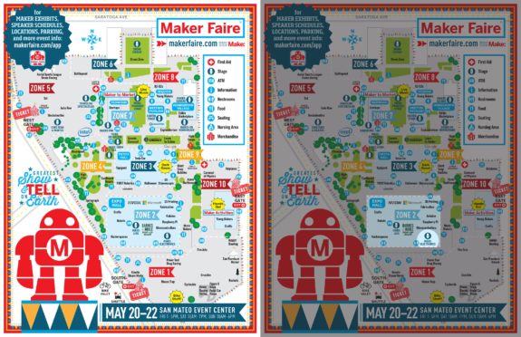
I’ll be doing a short presentation on how to build (and operate) a tiny drawing robot at Maker Faire Bay Area 2016.  My time slot is Sunday May 22, 2016 from 11:00am to 11:25am at the Make: Electronics stage in Zone 2 aka “Expo Hall.”  You can see where I’ve outlined Zone 2 and the Make: Electronics stage in the above picture.

If you’re around, I’d love to see you.  However, I know how hectic Maker Faire can be and how difficult it can be to get anywhere.  If you want to hang out, I’m planning to go to the Maker Paella Dinner on Friday night on the Maker Faire grounds and the Hackaday meetup on Saturday night O’Neill’s Irish Pub in San Mateo.1

  1. Tickets to the Hackaday meetup are free – just follow the link and RSVP []

Maker Faire Bay Area 2015!!!

Join me at Maker Faire 2015!!!

Join me at Maker Faire 2015!!!

Maker Faire Bay Area 2015 is just a few days away!  I hope you’re as excited as I am!

I’ve made some minor improvements to my large drawing robot and am going to bring a tiny drawing robot as well.  The changes to the big drawing robot are:

  1. “Feet” for Underside of Project Box
    1. My robot is built into a shallow wooden box.  On the top of that wooden box there is a “holder” for a roll of paper.  By adding little “feet,” as short as 1/8 inch or so, to the underside of the project box, the box no longer pushes against the roll of paper – which makes it easier to pull paper down when drawing.
  2. Revisions to Paper Roll Holder
    1. As it is, the paper roll holder is a little close to the project box, so the paper sometimes bumps against it.  This isn’t much of a problem, but one that can be eliminated easily.
    2. A notch in the top of the paper roll holder.  This way, rather than having to dismantle the robot, I can just lift the old paper roll out and drop in a new one.
  3. Batteries for Pen Holder
    1. The pen holder uses AA batteries, not for power, but for dead weight.  Right now the batteries are held in place by hot glue.  I would rather there was a slot on the holder for actually holding the batteries.

And, for those of you interested in seeing more of my TinyCNC, I’ll be bringing that too!  I’ve been working on a little something there as well.  Here’s what I’ve done:

  1. Mounted TinyCNC
    1. On a cigar box!  The TinyCNC is bolted to the top of a cigar box kindly donated by a local smoke shop.  A small solderless breadboard and Arduino now live inside the cigar box as well.
  2. Trying out New Interface
    1. I tried using the TinyCNC at first with an Arduino, feeding it Gcode-like commands over the serial interface.  Then I tried saving designs as coordinates and flashing an Adafruit Trinket with the coordinates and drawing that.  Since the Trinket doesn’t have a serial connection, this meant I lost a lot of the functionality of the tiny robot.
    2. This time I’m using a membrane 3×4 matrixed keypad to control the robot.  The keypad is also mounted to the cigar box.
  3. Trying out New Code
    1. I can get the Arduino to recognize keypresses reliably, but I can’t get the ‘bot to move in response… yet.  🙂  Heck, I still have almost 36 hours until showtime, which is plenty of time.  So far, it does absolutely nothing at all – except shudder.  I’m not that worried about it though, I can always go back to an older version of the Arduino sketch.

As far as actually showing a working demonstration of the TinyCNC, I have a few ideas.  Here’s what I’d like to show off, in descending order:

  1. Tiny robot, controlled by a numeric keypad, letting people draw on pieces of paper and take them home.
  2. Tiny robot, with several pre-programmed designs, letting people hit a number on a keypad, having it draw a pre-programmed design, and taking the piece of paper home.
  3. Tiny robot with a single push button mounted on box, which draws a single pre-programmed design when pressed, people take the piece of paper home.
  4. Tiny robot, connected to my laptop, drawing things sent from the laptop, and let people take a piece of paper with the drawing home.

What will be ready by Friday afternoon?  I have no idea!!!  You can either stop by and see for yourself or tune in on Monday night when I post a recap of the weekend.

The Tiniest Drawing Robot Actually Draws!

Tiny Drawing Robot satisfied with itself for having drawn a robot

Tiny Drawing Robot satisfied with itself for having drawn a robot

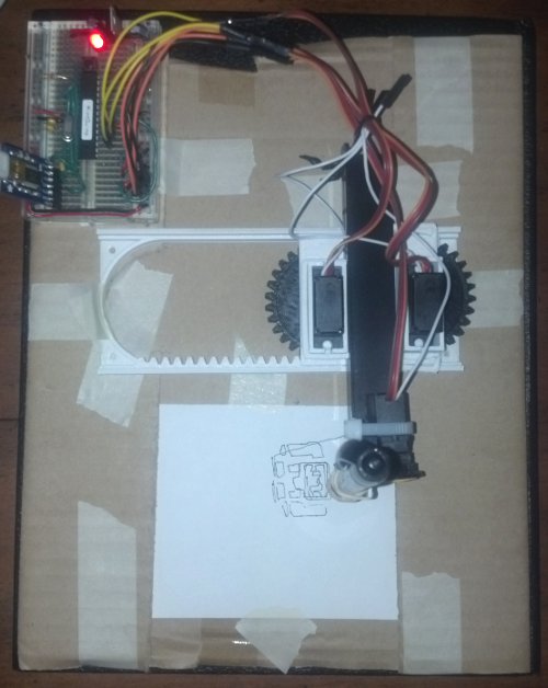
One of the most asked for features of this tiny drawing robot is that it needs software to actually draw things.  Well, wait no more!  The software to actually draw things is now a reality.  Above is a picture of the little drawing robot acting quite smug after having drawn a little copy of the Make robot.

While I’ve developed a basic “toolpath” to draw things, this is not yet a polished work.  There are lots of little hacks I’ve used to get the robot to work.  I’ll jot down as many as I can here so you can follow along at home if you like.  I anticipate developing a much better system very soon that won’t require as much fiddling.  🙂  For now, you can make your own tiny robot draw by following this rough guide:

  1. Download the TinyCNC-Gcode.ino Arduino sketch from Github and upload it to your Arduino.
    1. The Arduino sketch for the Tiny CNC has some hardcoded “limits” to the X, Y, and Z axes.  I added the limits of my own robot, but your mileage may vary.
    2. The robot treats the left most position with the Y axis totally retracted as the (0,0).  (Well, really, the X minimum and Y minimum position).  Thus, it doesn’t try to draw anything that’s not in the +X,+Y quadrant.
  2. Import or draw a picture in Inkscape.
  3. Export the drawing into Gcode using the MakerBot Unicorn Gcode Plugin by Marty McGuire.
    1. Since the plugin treats the center of the drawing as the coordinate (0,0), you’ll need to put your drawing in the top right quadrant of the picture.  I used a drawing area that was twice the height and width of my robot’s drawing area, so that the top right quadrant would be equal to the drawing area.
    2. It’s important to “break apart” the SVG drawing before you try to export the image to Gcode.  If you don’t you’ll probably end up with an error message and an empty Gcode file.
    3. Interestingly, since Marty’s Gcode plugin is written in Python and Python can communicate over USB with an Arduino, there’s no reason you couldn’t make the robot draw something directly from Inkscape.  Wouldn’t that be nifty?!
  4. Download the SendingSerial003.pde Processing sketch from Github and save it in your sketch folder.
    1. Ideally, the Processing sketch would send a Gcode command, wait for the robot to perform the action and then respond saying it was ready for the next command.  I just wanted something that works, so the Processing sketch just waits 1000 miliseconds between commands.  It’s a hack, but it’s a hack that seems to work well enough for now.
  5. Rename your Gcode file to “file.gcode” and place it in the same folder as the Processing sketch
    1. You could just change the filename in the Processing sketch too.
  6. Open the Processing and run the sketch
  7. The robot should leap into action drawing your design!

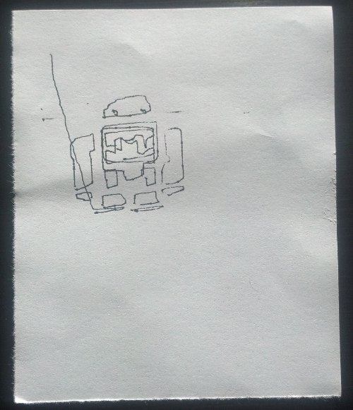
Here’s a photograph of just the drawing itself:

Make Robot, drawn with a robot made from Make and Adafruit parts, printed on a MakerBot

Make Robot, drawn with a robot made from Make and Adafruit parts, printed on a MakerBot

As you can tell, I haven’t spent a lot of time tuning my robot.  I know it is capable of smoother, more accurate drawing.  These are all things I’m hoping to improve with the next iteration of the design of the plastic parts.

If you’re interested in learning more about drawing robots, you might enjoy joining my mailing list about drawing robots.  No spam, just emails about drawing robots.  🙂

Competing Design Ideals in a Drawing Robot

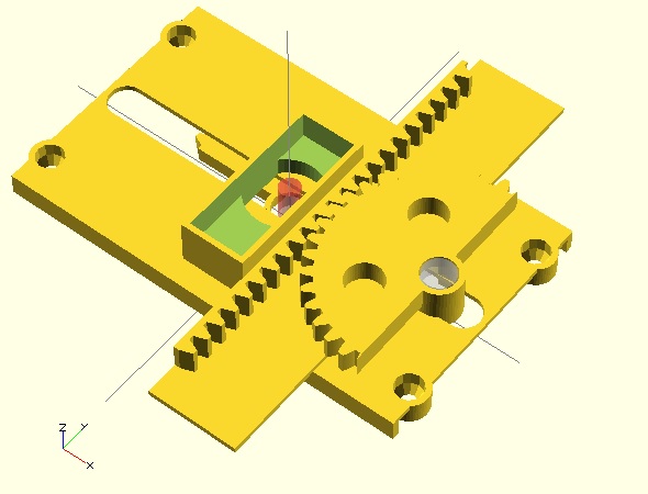
New possible design direction for the Tiny 3-Axis CNC

New possible design direction for the Tiny 3-Axis CNC

I find myself at a design crossroads, as it were, with the Tiny 3-Axis CNC.  There are certain improvements that I think are necessary to make the overall robot more functional and reliable.  However, to adjust these designs to accomplish these improvements would require a compromise of some part of the design ideals I’ve been employing so far.

One unintended consequence of having a low number of interlocking parts is that when I make a design change to one part of the robot, the design implications ripple throughout the rest of the robot.  Thankfully, this is made slightly easier by using OpenSCAD which automatically adjusts parts depending upon changes to variables.  These changes also have the side effect of making each version of the robot unique enough that almost no parts are compatible with other versions.  As a result, I’ve got a pile of parts from intermediate non-functional versions which don’t really work with any robot version.

In order to overcome some problems with the last design1 , I basically now need to choose what I value most:

  • Elegance.  Design elegance is a very murky and personal topic.  I think of design elegance as incorporating the fewest possible number of parts, simplicity, and (when possible) symmetry or the reuse of parts.  Even “simplicity” is a convoluted and subjective ideal.  I think of this as the least amount of plastic and least amount of complex features.
  • Low Part Count.  I love the idea of a super low part count.  If I were to print parts with support structures or had a very complex design for injection molding, I could probably reduce the part count to the absolute bare minimum possible number of parts – 7.2 However, if I try to make the parts easily printable without overhangs or support structures I have to increase the number of parts.
  • Easy to Print.  Even if a 3D printer is capable of printing with mild overhangs and support structures, a design is more easily printed if it doesn’t include such features.  It is very important to me that the parts are easy for people to replicate on their own.  For me, part of being “easy” to print is having as little plastic as is required.  The most recent stable version of this design takes about 2 hours of printing on my Replicator.  I think I can do better.
  • Easy to Assemble.  Generally, I’ve found the more complex and numerous the parts, the more difficult and less intuitive a thing is to assemble.  I would really like this robot to be able to be assembled by my 6 year old with minimal adult intervention.  She’s pretty good at building Lego designs from the graphical instructions and I’d like to have something similar here.  Fortunately, OpenSCAD make it really easy to create Ikea/Lego style graphical assembly instructions.

After discussing these issues with some friends, I think I’m going to sacrifice the super low part count as I push the design forward.  I don’t anticipate this will cause the design to have a higher plastic content – just a few more pieces.  Overall, if I had to sacrifice one particular design ideal in order to adhere more closely to the others, I would have to choose the super low part count.  After all, I could always publish an additional version that combines two or more parts into a version that could be printed with support structures.  🙂

  1. Principally the XYZ carriage tipping out of the X rack []
  2. I think this would require: the X rack/base, the X pinion, X motor mount, Y pinion, Y rack, Z pinion, and Z rack. []