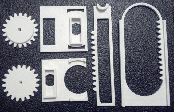
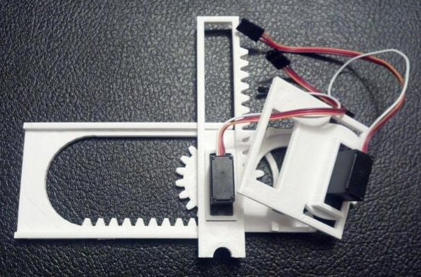
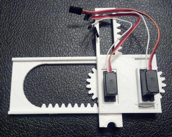
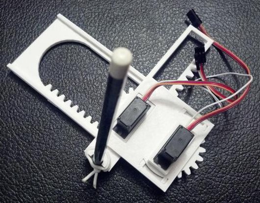
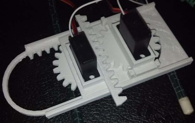
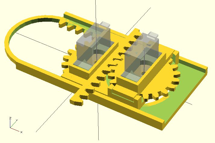
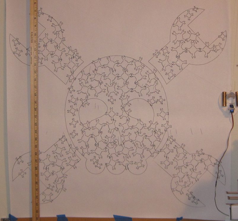
UPDATE: Here’s everything you need to to build a Tiny 3-Axis CNC robot using just 8 plastic pieces.
The above are nearly all the tools and parts you’ll need to build your own itty bitty CNC drawing robot.1 If you have a 3D printer and a spare Arduino, the rest of the parts should cost you around $20. Right now this robot only has two axes, but in the very near future I hope to add either a Z axis or a pen lift. Without further ado the tools needed are:
Tools
- One small precision screwdriver
Parts
- 2x Micro Servo Motors
- 6x 3D printed parts, downloaded from Thingiverse
- 1x rubber band
- 1x pencil
You’ll also need an Arduino, some wire to connect your servos to the Arduino, and a USB cable to communicate with the Arduino.
Assembly
Step 1: Print parts
There are only six printed parts necessary for this mini-CNC. If you’re careful, you’ll be able to fit all six on your MakerBot Replicator into a single build plate.
Step 2: Assemble the X axis stage
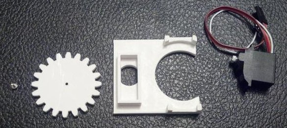
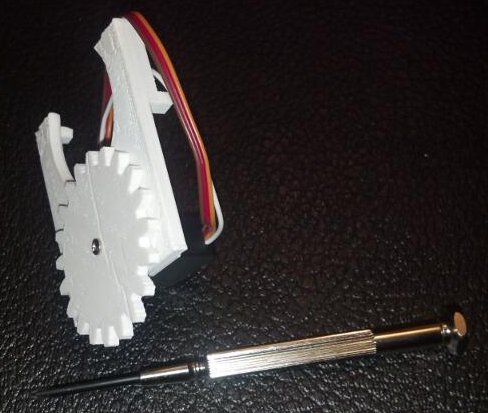
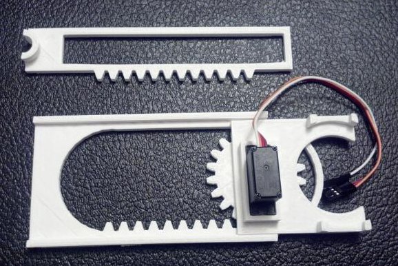
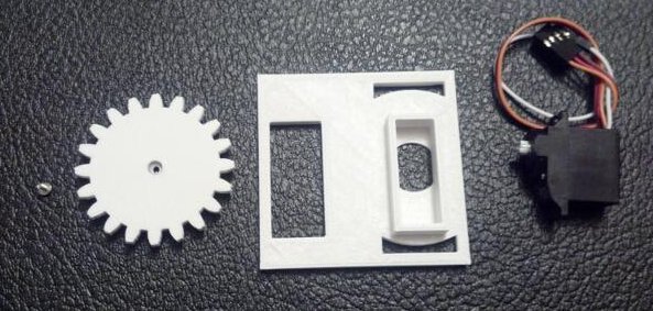
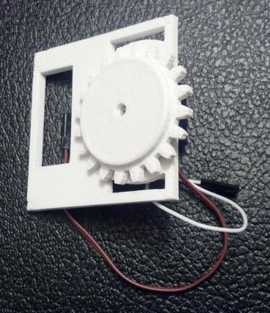
Grab your Micro Servo, the little screw that came with it, the flat gear (really, pinion), and the X axis stage. Just insert the Micro Servo into the X axis stage (it only fits one way), push the gear onto the Micro Servo’s motor shaft, and use the screw to secure the gear. It should look like this when done:
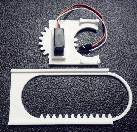
Step 3: Place the X axis stage on the large X axis rack
With the X axis stage gear-side down, rotate the gear clockwise until it stops.
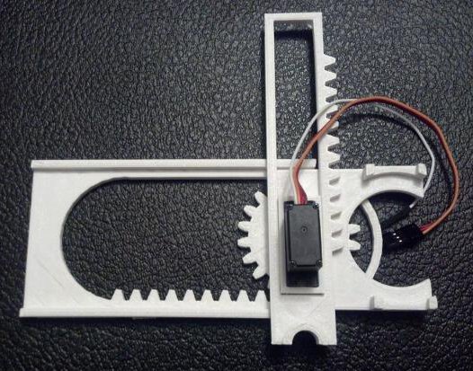
Then place the gear into the X axis rack as show.
Step 4: Place the Y axis rack
Locate the Y axis rack and place it over the X axis Servo Motor.
Like so.
Step 5: Assemble the Y axis stage
Just as with the X axis, gather the parts and assemble. This time, the servo motor goes into the stage (it only fits one way), the thick gear is then pushed onto the motor shaft with the gears toward the Y axis stage.
Like so.
Step 6: Add the Y axis stage
With the Y axis stage gear-side down, rotate the gear clockwise until it stops.
Route the X axis servo motor wires through the rectangular hole in the Y axis stage.
Place the Y axis stage down, with the large rectangular hole around the X axis motor.
Almost done!
Step 7: Ready the pen holder
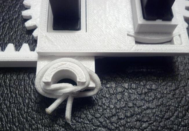
Place the rubber band around the pen holder as shown. You will probably have to wrap it around a few times.
Insert a pencil, pointy-bit down, into the pen holder.
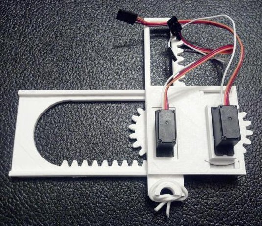
Step 8: Admire your work
Your robot is done!
Step 9: Wire Robot to Arduino
To save you a little bit of trouble reading the Arduino sketch and figuring it out, here’s how you would connect your robot to the Arduino:
- Use a piece of wire to connect the orange wire from the bottom X axis servo to pin 13 on the Arduino
- Use a piece of wire to connect the orange wire from the top Y axis servo to pin 12 on the Arduino
- Connect the brown wires from the servos to the ground pins on the Arduino
- Connect the red wires from the servos to the 5v pin on the Arduino
Step 10: Draw!
Download my Arduino sketch to operate this robot. The movements of the robot are hardcoded at the moment, so please check back for updates. Also, if you don’t tape or glue or somehow affix the little bot to a heavy surface, it will literally jerk itself all around the table. (Although, in retrospect, I could have made it draw slower…)
It’s a little difficult to see the lines as the robot is drawing, but it really is drawing a grid in this short video:
Room for Improvement
I hacked this little project together just in time for the MAKE and GE Robot Hacks presentation on 11/20/2013, so I know there’s lots of room for improvement. Here are some things I’m working on:
- An entire Z axis or pen lift mechanism using a third servo
- A better pen/pencil holder
- Actual code to use XY coordinates instead of directly specifying the degrees for each servo
- Actual motion control software from Processing or Python
- A few adjustments to the Y axis stage for a better fit
- Possibly thicker gears so that I can use set screws
- A variation on the gears to use less plastic
- Getting the robot to work with my Adafruit Trinket!
I hope you enjoyed this quick to print and easy to use desktop drawing CNC!
- You’ll also need an Arduino and some bits of wire [↩]


