Drawing Robot In A Box

Draw on the go with a small Arduino-powered CNC robot!

Draw on the go with a small Arduino-powered CNC robot!

Well, technically, ON a box.

The wiring is really simple.  A small breadboard is used connect Arduino pins 10, 11, 12, power and ground to the three servos.  The keypad is wired directly to pins 2 – 8 on the Arduino.  That’s it.

Wait... that's all there is to it?!?

Wait… that’s all there is to it?!?

Of course, it doesn’t work.  Yet.  🙂

Tiny Drawing Robot Updates, Incremental Progress, and More!

This slideshow requires JavaScript.


It’s been about a week since my last blog post and I’ve really been enjoying working on all aspects of the Tiny CNC.  With the year winding to a close, I wanted to squeeze in one last update.

The really cool thing about working on a robotics project from the ground up is that you can work totally different aspects of the project, whatever happens to interest you at that moment.  Sometimes 3D design appeals to me, other times working on Arduino or Processing code.  And then sometimes working on making the project really real by contacting suppliers to source parts for kits.  Here’s what’s going on now:

  • Adventures with Online Ordering.  I pulled the trigger and bought 100 micro servo motors.  I’m hoping that once I get this tiny drawing robot’s designs a little more finalized some people will be interested in having me create kits for them.  I simply cannot tell you how much fun it was to open up a box fresh from China stuffed with 100 motors.1 I spent several days shopping around on Alibaba and trying to reach out directly to motor manufacturers and in the end I finally placed an order with a “distributor/middleman” because it was a decent deal and he could ship immediately.  I know I overpaid a little, but this is kind of a test run anyhow.  With 100 micro servo motors, and each robot taking 3 motors, I’ll be able to create at most about 30 bare-bones kits for sale.
  • Micro Servo Motors.  These are the really common, and reasonably cheap, TowerPro SG90 motors that you see for sale everywhere.  People who have printed the Tiny CNC on Thingiverse to date have had to try to get their more standard micro servos to work in my designs that were made for the more badass Batan 2122 analog feedback micro servos that I received courtesy of Adafruit and Make.2
  • Arduino Code.  With the gentle prodding of TechNinja42, I created a Github account where I’ve uploaded some of the Arduino code I’ve been experimenting with so far.  While I have uploaded my prior sketches to Thingiverse, Github does seem like a better place to share these files which are changing quickly.  If you grab this code and load it up, you’ll be able to control your Tiny CNC drawing robot just by using the Arduino’s serial monitor and the WASD for directional control and OL to raise and lower the Z axis.
  • Teaching Programming to a 6 Year Old.  Christmas day was the first time I wrote some Arduino code that actually made my robot do something interesting.  Long story short, I actually got my daughter on the first step to programming.  I had her draw a simple shape on some graph paper, we took down the coordinates, plugged the coordinates into the Arduino code, and then the little robot got to work.  We had a great time creating the program and an even better time watching the robot repeat her drawing, pause for five seconds, and do it again.  The reason for the five-second pause was so that we could slip a sheet of paper into the robot, have it draw something, then pull the paper out.  I can’t wait to get this robot drawing more complex pictures.  🙂
  • Tiny 3-Axis CNC Redesign, Again.  I’ve already started revising my designs to work with the Tower Pro SG90 motor form factors, so it will be easier for everyone to print and build their own drawing robots.  I’ve added lots of improvements based on feedback from those who have printed their own, and I’m very nearly done with this latest version.  So far it is shorter, probably uses less plastic, should be offer more stable and accurate drawing, and uses one more plastic piece than prior versions – all while slightly increasing the drawing area.  Since I offered a sneak peak at this design in progress in an earlier post, I’ll leave off with a glimpse of this design-in-progress.
Tiny 3-Axis CNC version 0.34

Tiny 3-Axis CNC version 0.34

  1. And one Arduino Uno of dubious authenticity []
  2. I call these motors badass because they’ve got metal gears inside rather than plastic, analog feedback so they can sense and report their position back to the microcontroller, and cost $15 each []

Tiny CNC Software Update

Stephen's version 0.18 robot drawing away!

Stephen’s version 0.18 robot drawing away!

I want to start this post with a shout out to Stephen Laporte.  I met Stephen at the Bay Area 2013 Maker Faire when he came over from the Wikipedia booth to see if I could draw a giant Wikipedia logo for their booth with my large PlotterBot.  Stephen was also the winning bidder for the version 0.18 parts I listed for sale on eBay a few weeks ago.  I shipped out the parts as soon as the auction ended and he got them the Friday after Thanksgiving.

Now, here’s the cool part…  While I’ve been busy hammering away at the design aspects of this tiny robot, Stephen put together some software to get it drawing something more than grids!  He has graciously shared his Arduino and Python code on Github for everyone to use.  With just a few lines of code, you could easily add in support for the brand-spanking-new third axis.

Tiny CNC – now a 3 Axis CNC!

Tiny CNC - Now with 50% more axes!

Tiny CNC – Now with 50% more axes!

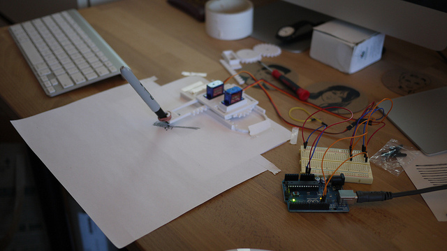
With some helpful feedback from several readers, I’ve been working on improving the design for the Tiny CNC.  Last night I was able to print the latest version and assemble the robot.

Here’s a quick tour of the new features:

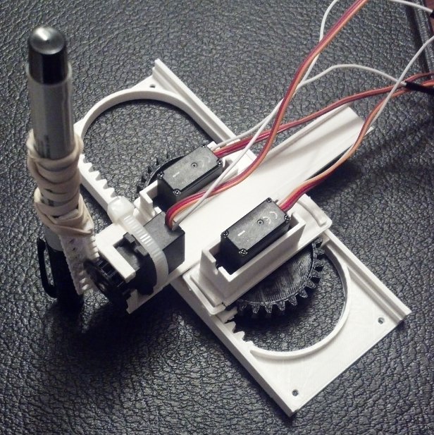
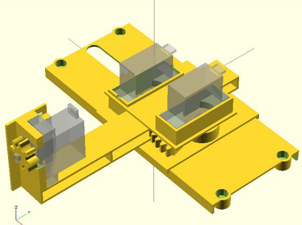
  • Z-Axis / Pen Lift.  This is by far the most requested feature – and the aspect of this robot I was most anxious to complete.  In order work within my design ideals (low part counts, easy printing, etc) I had to make a concession.  To fit the Z axis between the X and Y motors, I had to reduce the size of the Z axis gear. The result is that the Z axis can only lift by about 15mm.  Thus, the robot has a maximum operational area of 76mm x 76 mm x 15 mm.1 While the Z axis lift isn’t anything spectacular, it is sufficient to have an actual drawing robot.
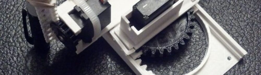
  • Low Part Count.  The new design consists of 7 unique printed plastic parts, one of which needs to be printed twice, for a total of 8 parts.  Designing for a low part count meant that I had to design some fairly (for me) complex parts.
  • Easy Printing. I designed all seven parts to be printed easily without support.  While there have been vast improvements in 3D printing support structure technology in just the last year, you won’t need any of that.  These parts should be easy to print with just about any machine.
  • Snap-Fit Design (mostly).  I personally enjoy printed parts that just fit together without the need for additional tools and materials.  While there’s more work to be done on the design to make sure the parts have a better fit, this iteration just needs to be snap fit together.  As you build the robot several of the pieces help keep earlier pieces in place.  The only part that doesn’t snap-fit in place is the Z axis motor – which requires a single zip tie.
  • Mounting Holes.  This version includes a much requested feature – mounting holes.  The entire plastic frame is extremely lightweight and the motors can easily make the entire robot hop around.  The mounting holes will allow the robot to be bolted or screwed directly to a surface.

To Do List:

  • Herringbone Rack and Pinions.  It’s still possible to include these – and I’ve even already written the code to incorporate them.  However, I’m going to hold off integrating this feature until I can actually draw something.
  • Improved Y Rack.  The Y rack I am using had one end that lifted off the build platform slightly and is consequently curved.  A better version of this part would be wider to eliminate some wobble.
  • Balance Y Rack.  As mentioned earlier, the entire robot is very light.  As the Y axis is fully extended, the Z axis motor can cause the entire robot to tip over or the X stage to pop off the X rack.  If there was a weight of some sort at the other end of the Y rack, this may not be such a problem.
  • Better Z Axis Holder.  Right now the Z axis rack is basically a rack with a plank with holes in it.  While it’s not really pretty, it can get the job done.  I would like to design and incorporate something that’s a lot more aesthetically pleasing and functional.

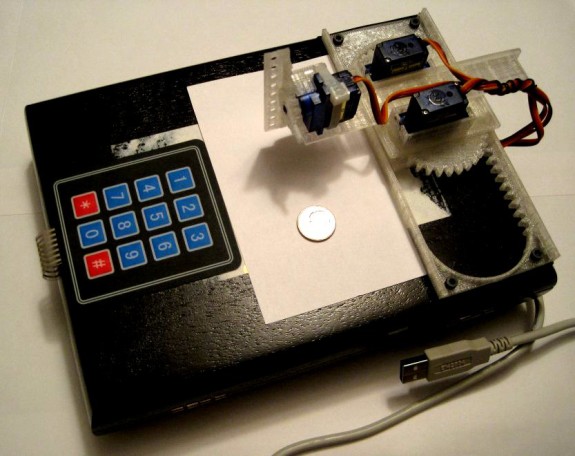
Now that I have a robot again, I’m looking forward to trying to draw something with it!

In the meantime, if you’d like to build your own, download the parts from Thingiverse!

  1. This is about 3″ x 3″ x 0.5″, for you imperialists out there []