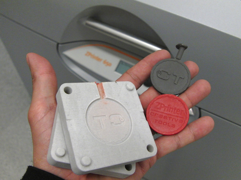
I had always assumed injection molding was a pretty straightforward process.1 You send your digital files to the injection molder, you pay a bunch of money, and plastic parts show up. While looking into the process of injection molding, I discovered there are all kinds of design requirements.
- Uniform Thickness. Apparently having a non-uniform thickness to plastic injection molded parts causes lots of problem. The plastic can flow into the mold unevenly and cause bubbles or voids. The thinner parts would cool quicker and the thicker parts would stay warm longer, causing the part to warp as it cools.
- Draft. Apparently all parts that are injection molded require some amount of “draft.” This means that a part should be tapered outward slightly – so that it can slide easier out of the mold and incur less friction as the mold parts slide together and apart. The various resources I’ve found suggest a minimum draft angle of 0.5 degrees to as much as 5 degrees for parts with lots of surface texture elements.
- Part Radiusing. Since the plastic shot into a mold is basically a viscous liquid, it flows better around curved corners and has a difficult time flowing around sharp angles. The guides online suggest that internal curves should have an internal radius of 0.5 times the wall thickness and an external radius of 1.5 times the wall thickness. Plus, proper radiusing means consistent wall thickness, even around part corners.
- Coring Out. The process of removing excess material, leaving the bare minimum uniform wall thickness in walls and ribs for strength. This allows the finished part to be of uniform thickness to prevent uneven shrinking and internal part stress.
- Radiused Corners. As a part’s geometry is carved by a CNC mill out of the metal mold the CNC can only carve with a minimum diameter equal to the CNC’s bit. This means corners won’t ever be true corners, but rather small curved internal corners.
Interestingly, these design requirements also explain why so many plastic parts are basically shells. I had always assumed this was done to reduce plastic and cost.
- Photo courtesy of Creative Tools [↩]


You initial designs where also easy to print on a laser cutter. Keeping it simple *is* possible. Printing using a laser cutter wil also make it better suited for “mass” protuction.
Perhaps you need to go that way? (also but I said this before) try replacing the servo’s with stepper motors.
An ohter “easy” trick to keep things simple is move the platform
where the drawing is drawn. You can for example move the platform over the x-axis. that will keep the design of the y and z axis easy.
This is what printrbot simple is doing
http://printrbot.com/shop/printrbot-simple/
moving over a single axis can be done using just a rack/pinion combo.
Keep up the great work!
@keesj: While a simple lasercut design is certainly possible, I think it would involve many more parts and require a lot more hardware than a 3D printable design. However, I’m happy to experiment with new designs!