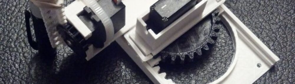

Fully assembled 3-axis CNC robot, with pen
The following is my entry of a small 3-axis CNC robotics platform into the African Robotics Network (AFRON) Ultra Affordable Educational Robot 2013 Design Challenge.
Table Of Contents
Distinction from Drawing Robots
Designed to be Easily Reproduced
Flexible Material Requirements
Repurposed and Recycled Materials
3. Drawings with Dimensions, Physical Properties
4. Step-by-Step Assembly Instructions
Photograph and Descriptions of All Materials Required
Wiring the robot to an Arduino microcontroller
Learning micro servo control with an Arduino
Developing a test 3D printable design
Refining the 3D printable design
Incorporating community improvements
Testing alternate recycled and repurposed materials in with the design
6. Pictures and Video of Robot in Action
7. Proposed Design Enhancements
Reduced plastic usage to make the robot more cost effective to manufacture
Herringbone teeth to increase effectiveness
Constrained X axis to increase effectiveness
Design changes required for injection molding to improve ease of manufacturing
Soldering connection would improve the robustness of the robot
Removing need for set screws to improve the ease of assembly
8. Hardware Enhancements: Conclusion
1. Software User Guide Documentation
2. Links to the Open Source Software
3. Proposed and Planned Software Enhancements
Integration with other open source CNC robotic platforms
Reduced microcontroller sketch size and compatibility with more open source Arduino derivatives
Designing a Robot (or Accessories)
5. Community Challenge / Student Workshop
1. High-Level Description
The Tiny CNC robot, despite its minimal design, is a versatile 3-axis CNC robotics platform which can be customized to perform a variety of useful functions. To demonstrate its versatility, I have augmented it with a pen to serve as a small drawing robot. Several years ago I had seen a video and photographs of a similar project and always wanted to build a similar robot for myself. Using the concept of the Piccolo as a source of inspiration, I set about to build a small 3-axis CNC robot of my own design.
-
Distinction from Drawing Robots
Most drawing robots utilize a pen lift mechanism, usually by connecting a pen or drawing utensil to a servo motor. While this attachment method is sufficient to enable the machine to lift the drawing implement off the drawing surface, it is usually lifted in an arc – as it follows the servo motor’s rotation. Since the Tiny CNC has an actual Z axis mechanism, instead of lifting a pen in an arc, a pen be attached to the Z-axis and raised or lowered in a vertical orientation. Being able to raise the Z axis vertically makes the robot far more useful than a simple drawing robot since it could be augmented to operate a syringe or needle which would require a perfectly linear motion, rather than an arc.
-
Rack and Pinion Design
Many majority of CNC machines use heavy, expensive, and/or difficult to source parts such as toothed gears, expensive precision toothed timing belts, straight precision rods. Unlike these much more expensive robots, the Tiny CNC utilizes a rack and pinion design to convert the rotational motion of the micro servo motors into a linear motion. This design entirely eliminates the need for many expensive or difficult to find parts.
-
Low Part Count
Almost all CNC machines use a large number of parts including nuts, bolts, screws, and fasteners. Even simpler CNC machines, such as the PrintrBot Simple, which use tensioned fishing line instead of timing belts, require hundreds of parts. By using 3D printing to create parts that interlock and snap-fit together, the Tiny CNC can be built with little more than 8 printed plastic parts, 3 micro servo motors, and one zip tie.
-
Designed to be Easily Reproduced
Although 3D printing allows for the fabrication of complex designs including overhangs and undercuts, which are more difficult for resin casting, injection molding, and milling production, the Tiny CNC design specifically eschews these features to allow for the parts to be produced easily by many different fabrication techniques. Additionally, the parts were designed to not require any support structures, which makes them easier to produce on even simpler 3D printing machines.
-
Flexible Material Requirements
The 8 plastic parts of the robot could be made out of nearly any rigid material, not just plastic. Additionally, the sole “fastener” in the list of materials, a zip tie used to secure the Z axis motor, could be replaced with many other things – a rubber band, piece of elastic, a piece of cord, a twist-tie, or even a simple piece of wire. For more permanency, someone could just glue, super glue, or hot glue the motor in place.
-
Versatile Platform
As mentioned above, as a 3-axis CNC, this robot is capable of more than just drawing. By using a fourth servo, a robotic gripper could be attached to the Z axis to create a sorting robot. One person suggested using this robotic platform as a phage/bacteria printer. The designer of the WaterColorBot, Super Awesome Sylvia, has suggested using this robotic platform as a small watercolor painting robot.
-
Real-World Testing
At the time of this writing, three iterations of this robot (a 1.5-axis version, a 2-axis version and a 3-axis version) have been published online on Thingiverse. Together they have been downloaded a total of 6981 times, with 10 people around the world who have posted photos of their copies.
-
Collaborative
The latest versions of this robot incorporate design suggestions, requests, and feedback from users – such as including mounting holes, improving the pen holder, and including a Z-axis. The latest Arduino sketch uses a modification of the Gcode interpreter written by a contributor. The Gcode is obtained by using an open source plugin to convert SVG vector graphics files in Inkscape (itself an open source program). The Arduino sketch, was has been shared on Github, has been contributed to by the creators of another open source project, WaterColorBot to allow the software that runs that robot to power this tiny CNC as well.
-
Repurposed and Recycled Materials
In order to reduce slippage between the micro servo’s gearshaft and the printed plastic gears, I initially used a piece of a thick rubber band as a gasket. Since then, I have discovered that the discarded extra parts from foam-rubber stickers, which are otherwise trash, serve this purpose even better than the the rubber bands. Twist ties and/or pieces of scrap wire can be used to affix a servo motor into the Z axis.
-
Minimal Tools
The only tool strictly required to create this robot is a small Phillips head screwdriver – used to tighten the micro servo set screws. While a pair of scissors or wire cutters come in handy to clip the excess zip ties, they are not required. Through careful design choices, it is conceivable that even the screwdriver may not be required. Since the robot doesn’t require soldering, soldering irons, or sharp blades, it could be built by any child responsible enough to operate a screwdriver safely and trusted not to swallow small parts.
-
Age Appropriate
With the robot being comprised of very few parts and requiring reasonably safe tools, it can be assembled by even young children. Unlike standard CNC machines using powerful stepper motors, this robot uses low power micro servo motors that are not likely to be able to harm small inquisitive fingers.
2. Hardware Enhancements
Prior to submission, I received clarification that an entirely new robot could be submitted in the “hardware enhancement” challenge as a complete re-design.
1. List of Parts
With the exception of the major parts (plastic components and micro servo motors) all of the remaining parts can be salvaged or substituted for easily salvaged materials. Alternate materials are listed in the Notes section.
| Part | # | Source | Price | Notes |
| Plastic parts | 8 parts (22.2g of plastic) | Thingiverse | $0.96 (but potentially as low as $0.07) | The total weight of all printed plastic parts is approximately 22.2g.1 The MakerBot ABS plastic I used cost $43.00/kg at the time of purchase. 45 sets of plastic parts could be produced with a single spool of ABS, leading to a per set plastic cost of $0.96.It is possible to source plastic filament for a 3D printer cheaper from other suppliers. Suppliers on Amazon offer 1kg spools for as little as $17.99 leading to a per set price of $0.40. Suppliers from Alibaba offer prices for 1kg spools of PLA plastic as low as $5.
In researching injection molding, I was quoted $1.40 per pound for ABS by Crown Plastics. At $1.40 per pound, I would estimate a per set price of approximately $0.07. This would of course require a large investment in injection molds. If injection molding is considered part of the “tool” cost, then this is an extremely cost-effective option. If these plastic parts are unavailable, it may be possible to use the parts from a discarded CD-ROM or CD/DVD player tray to construct a similar robot. These plastic tray mechanisms usually incorporate a rack and have numerous pinions and gears inside. |
| Micro servo motors, 9g | 3 | Alibaba | Donated! (but potentially from as low as $0.60 to $4.50) | Sellers on Alibaba Express offer micro servo motors for as little as $1.65/each. With some negotiating I was able to make a medium sized purchase through Alibaba for a per motor price of $1.50. When I received the package it came with a packing slip indicating the retailer who sold me the motors only paid $1.00 per motor. Having contacted the wholesaler, they have confirmed they can sell these motors for $1.00 directly to me.2 Similar suitable micro servo motors can be found on Amazon.com for $1.08, on HobbyKing.com for $2.09.According to Chris Anderson, small motors can be sourced from the manufacturers or wholesalers for as little as $0.20.
I personally used micro servo motors that were donated by Make Magazine as part of the Robot Hacks challenge. If micro servo motors are unavailable, the plastic parts could be modified to accept very small small stepper motors such as one might find in discarded electronics. |
| USB cable | 1 | Recycled! | $0.00 – $0.30 | I happen to have lots of USB cables of various connections around. The one I’m using was originally from an external hard drive.These are also typically plentiful in most work places. The precise kind of USB cable required would depend on the kind of microprocessor used.
However, most microcontroller can have the four wires from a USB cable connected or soldered directly into them. With the proliferation of wireless/Bluetooth mice, keyboards, speakers, other USB computer peripherals, and even some USB charging cables most offices and schools probably have a surplus of devices that have USB cables. By taking USB cable with a USB A connector on one side and cutting off the other end, the four wires inside the insulated cable can be exposed and soldered or wired directly into a microcontroller. While the precise USB cable required would be dictated by your microcontroller, the above method of cutting off and soldering the wires into the microcontroller can make pretty much any USB cable work. If a USB cable must be purchased, they can be found on Alibaba.com for as little as $0.30, Digikey starting at $0.70, and Amazon.com beginning at $2.41. |
| Foam rubber sticker | 3 | Recycled! | $0.00 – $0.002 | The punch-outs from foam rubber stickers are essentially trash that is generally discarded. These scrap pieces make for excellent gaskets between the plastic pinions and the micro servo set screws.
Adhesive weatherstripping and foam tape would also make ideal choices. Requiring less than 1″ per robot, a single roll of such tape would be enough for 204 robots and cost $2.98 total, for a per-robot cost of about 1.4 cents.I have tested both other pieces of non-adhesive foam rubber and pieces of rubber bands. Both of these would work as an alternative, can be found as discards or scrap, and would work slightly better with a small amount of adhesive. Although I haven’t tried this, I suspect a piece of scrap fabric covered in sap, pitch, or tar would probably work as an excellent gasket between the motor set screw and the pinions. The amount of foam sticker material required is almost negligible. I weighed an entire owl shaped sticker, which is for more than 10 robots, and found it weighed 0.3g. A plastic tub of 5 oz of such stickers through Amazon would cost $8.34. A single tub would be enough for 4,725 robots. I would estimate the foam sticker cost per robot to a little less than 1/5 of a penny. These same kinds of scrap foam shapes can also be found as part of scrapbooking materials, in craft stores, or at various other online retailers. |
| Rubber band | 1 | Found! | $0.00 – $0.004 | A rubber band can be used to secure a pen (or pencil, brush, crayon, or other item) to the Z axis. Rubber bands can be salvaged from many sources including newspapers or from bags of groceries. I found my own rubber band in the family junk drawer.They are basically ubiquitous in any office or school setting. In a pinch, Kinko’s and other photocopy and print shops always has a large supply of rubber bands near their paper clips and staples for patrons to use in organizing their printed materials.
A twist-tie or piece of wire can be used in place of the rubber band. Twist-ties can be found on bags of bread or other groceries. Twist ties can be found included in boxes of garbage bags or in large supply in grocery stories. If twist-ties and rubber bands are not available, tape, hot glue, insulated wire, uninsulated wire, yarn (possibly from a discarded sweater?), thread, cord, or even a thin strip of fabric could be used to affix the pen in place.If absolutely no free alternatives can be found, rubber bands can be purchased in bulk at any office supply store or many places online. Amazon carries bulk rubber bands (4800) for as little as $19.95, coming to about $0.004 per rubber band. |
| Insulated wire | 1 | Donated! | $0.00 – $0.49 | Insulated wire is not strictly required for this robot. By simply cutting the plastic connectors off the ends of the micro servo motor leads, the wires can be stripped and exposed for making electrical connections. However, finding additional wire means this extra step won’t be necessary.
Depending upon your robot’s wiring arrangement, you may need up to about 3 feet of thin insulated wire. Ideally, this would be solid core insulated wire if you are using a breadboard or other temporary setup and stranded insulated wire if they will be soldered in place. It is also helpful to have the wire in at least three distinct colors. Insulated wire is one of the more easily scavenged pieces. Lengths of insulated wire can be found inside discarded electronics such as fax machines, printers, fax machines, scanners, DVD and VHS players, televisions and old stereos. In the past I have used twist ties in place of short pieces of insulated wire. Twist ties are just pieces of thin wire sandwiched between pieces of paper or plastic, meant to give the wire something to grip on – but they also serve as suitable insulation.If you absolutely cannot find any kind of alternative to purchasing insulated wire, it can be found as speaker wire or hook up wire in any hardware or electronics store. On Amazon 100 feet of such wire costs $16.17 and would be more than enough for 33 robots, at a per-robot cost of about $0.49. |
| Tape | 4 | Found! | $0.00 – $0.01 | The robot is so lightweight, that a sudden movement of the motors can cause the entire robot to be jerked entirely off the drawing surface. If the robot is operated slowly, this isn’t a problem. If operated close to it’s top speed, it should be attached to a rigid surface. I used masking tape to affix my robot to a sheet of cardboard.Nails or screws could be used with the mounting holes to affix the robot in place. Screws left over from dismantling old electronics would be perfectly suitable. Nails are fairly easy to find scattered around any construction site.
If nails and screws are unavailable, a hole could be punched through the cardboard in line with the mounting holes in the plastic parts and insulated wire, twist ties, twine, yarn, thread, or thin strips of fabric could be used to affix the robot in place.If absolutely no free alternatives are available, more than 60 yards of tape can be purchased from Amazon for $2.27. Since only about 6″ of tape would be required, a single roll is enough for 360 robots and would cost less than $0.01 per robot. |
| Cardboard | 1 | Recycled! | $0.00 | Any sheet of cardboard larger than the robot’s footprint plus the drawing area would make an appropriate mounting surface for the robot. If cardboard is unavailable a piece of plywood, book, or sheet of any kind of rigid material such as metal or plastic. Plexiglass, corrugated sheets of plastic (commonly used in cheap outdoor signs – just wait until the next election cycle!) or road or street signs would all work. There’s also no reason the robot couldn’t just be attached directly to a table or desk.
Throughout this list of parts I have provided links to numerous online retailers that offer parts for sale. It is virtually certain that an order of any parts would be delivered inside a cardboard box. It’s basically impossible to embark upon building this robot without sourcing cardboard. |
| Zip tie | 1 | Purchased | $0.00 – $0.02 | A single zip tie is used to secure a single servo motor into the Z-axis position.I purchased a big container of assorted zip ties many years ago from the local hardware store. Unfortunately, I don’t have any way of knowing how much I paid for these. Careful sourcing on Amazon can get you a 100-pack of zip ties for $1.69, or less than $0.02 per piece.
As with several other parts above, there is no special requirement of a zip tie here. It could be replaced with a rubber band, twist tie, string, thread, yarn, wire, insulated wire, or thin strip of fabric. |
| Paper (at least 3″x 3″) | 1 | Purchased / Recycled | $0.00 – $0.001 | Any kind of paper, cardboard, card stock, plank of wood, or any flat surface would work as an acceptable drawing surface. One could use discarded gift wrapping paper, packaging materials, envelopes, junk mail, brochures, flyers, catalogs, or just regular printer and photocopier paper.Amazon carries reams of 500 sheets of paper for as little as $7.00. This current version of this robot has an effective drawing area of about 3″ wide by 2″ tall. A single 8-1/2″x11″ sheet of paper is sufficient for about 16 separate drawings.This would be considered a “consumable” for the purposes of this challenge. |
| Pen | 1 | Donated! | $0.00 – $1.29 | Like most households, I have a lot of spare pens lying around. Pens, even very nice pens, are commonly branded give-away items for many businesses. It should be very easy to find a business willing to donate a single pen.
However, not all pens are created equally. A ball point pen will generally not work as well as a liquid ink or gel ink pen. A marker, permanent or otherwise, will tend to bleed more than a liquid or gel ink pen if the robot is not operated quickly enough. Interestingly, since the robot is designed to hold a pen vertically, it can make use of pens that are nearly empty and not as useful in handwriting – where the pen is held at an angle. Also, since only the actual ink cartridge is required for this robot, any pen that has a broken spring mechanism or is otherwise not useful or awkward for handwriting can be recycled to be used with this robot. A 12-pack of refills for a decent gel ink pen on Amazon would cost $15.48, or $1.29 per pen.This would be considered a “consumable” for the purposes of this challenge. |
| Microcontroller | 1 | Donated! | $0.00 ($6.36 – $22.00) | According to the rules applicants are encouraged to “try to stay below 20 USD, excluding computing.” In seeking clarification of these rules, I was advised that computing refers to any kind of computing.I have operated this robot using a donated Arduino Uno (courtesy of Make Magazine’s Robot Hacks challenge), a Mintduino plus Adafruit FTDI Friend (courtesy of Make Magazine for prototyping and building the Beatband Sleeve), and an Adafruit Trinket 5v (a prize from the Hackaday and Adafruit Trinket challenge). I have also operated this robot using a Digistump Digispark ($9.33/board from my Kickstarter pledge, but now $8.95 each on their website).While I happen to now have accumulated a few extra microcontrollers which I’m using with this project, I don’t expect everyone to have the same equipment. These various solutions have their pros and cons:
|
| Breadboard
(Optional) |
0 – 1 | Donated! | $0.00 – $2.02 | This is optional.
A breadboard is extremely useful in prototyping and testing a robot. A mini breadboard on Amazon could cost as little as $10.06 for a pack of 5, with a per-unit cost of $2.02.While it is entirely possible to assemble a working model of this robot without soldering connections or using a breadboard, and simply twisting wires together instead, one of these two methods will make the job a lot easier and more robust. |
| Solder
(Optional) |
0 – 0.1g | Purchased | $0.00 – $0.01 | This is optional.
If this robot is assembled either with a breadboard or by twisting wires together, there is no need for solder. There just aren’t a lot of electrical connections required in connecting three micro servos to a microcontroller. However, for a more permanent setup, soldered connections would be ideal. It’s difficult to assess just how much solder would be required to build a single such robot. If one made it their goal to be extremely cognizant of the solder used, there could be as few as 9 soldered joints with very careful planning. On Amazon 37g of solder can be purchased for $5.53 – which is probably enough for several hundred robots at a cost of between $0.01 and $0.05 each. |
My actual out-of-pocket costs for building one copy of this robot was around $0.96 (just the plastic) since I happened to have absolutely everything else lying around. Someone in a similar context to myself3 would really only need to produce the plastic parts with a 3D printer, source some micro servo motors, and get a cheap microcontroller to build their own such robot.
Assuming a person in a similar context to myself did a careful job of sourcing the parts4 they could produce a robot for $0.40 using cheap 3D printer plastic filament, $3.00 for micro servo motors, and $6.36 for the cheapest possible Arduino alternative with an onboard integrated FTDI interface, for a total cost of about $9.76. If the FTDI interface is considered part of the tool cost, rather than the materials cost, then the robot could be built for $0.40 in plastic, $3.00 for three motors, and $3.00 for a bare-bones Arduino for a total cost of about $6.40.
2. List of Tools/Equipment
The plastic parts of this robot were specifically designed to dramatically reduce or entirely eliminate the need for fasteners and tools. The 8 plastic parts snap together tightly and stay together largely to the the friction-fit of the plastic parts and the way in which several of them interlock with one another and are kept in place by trapping other parts with the set screws that come with the micro servos.
The complexity of the build of this robot, and the tidiness of the finished product, largely depends on the kinds of parts available to the person assembling and how much they’re willing to spend on a few other minor parts. While the robot could be built as cheaply as $6.40, this requires a much larger investment in time than if they were willing to spend up to $15.00.
| Tool | # | Price | Notes |
| Small Phillips head screwdriver | 1 | $1.00 – $3.91 | A small Phillips head screwdriver or precision screwdriver is necessary to secure the servo motor set screw in place on the plastic pinion.I’ve seen small screwdriver sets for sale at the local hardware store for as little as $1. However, on Amazon I was able to find a large 11-piece set for $3.91.
One screwdriver could be used to build an unlimited number of robots. |
| Scissors or wire cutters
(Optional) |
1 | $2.99 | This is optional.
Scissors or wire cutters are helpful in cutting cardboard, paper, excess plastic from zip ties, wires, and can serve as wire strippers in a pinch. They can be purchased from Amazon for as little as $2.99. A single pair can be used to build an unlimited number of robots. |
| Wire strippers
(Optional) |
1 | $5.01 | This is optional.
Wire strippers can be very helpful in the construction of this robot to … strip wires. Although scissors and wire cutters can be used, actual wire strippers are just better suited to the task. A pair can be found on Amazon for as little as $5.01. A single pair can be used to build an unlimited number of robots. |
| Soldering iron
(Optional) |
1 | $5.42 | This is optional.
A soldering iron is very useful if you’re looking to create a permanent connection for the parts of this robot. Doing so will make the electrical connections much more robust and reliable. A basic soldering iron can be found on Amazon for $5.42. A single soldering iron could be used to build an unlimited number of robots. |
| FTDI Friend
(Optional) |
1 per robot | $11.80 | This is optional, depending upon your microcontroller and software choices.
If the user decides to store drawing designs inside the microcontroller, there is no need for an FTDI cable – as the robot could be wired directly to a USB cable for 5v power. However, this isn’t as interesting as being able to send commands over the USB cable.If a microcontroller without an FTDI interface is used in this project, an FTDI interface device, such as the Adafruit FTDI Friend will be required to program the Arduino microcontroller, provide power to the project, and send commands to the robot. A single FTDI interface device is necessary to program certain microcontrollers (such as the Mintduino, the Diavolino, or bare bones Arduino), provide power, and send commands. |
| USB cable
(Possibly) |
1 per robot | Recycled | In some ways the USB cable can be considered a tool (for programming, sending commands, providing power) and in other ways it can be considered part of the materials necessary for building the robot.
Further details regarding the availability, pricing, and possible free sources of USB cables are provided in the “list of parts” section above. |
3. Drawings with Dimensions, Physical Properties
As the challenge specifically requires drawings with dimensions, pictures of the 8 plastic parts are included here with their exterior dimensions. An STL file containing the exact dimensions for all plastic parts required for this robot are freely available for download on Thingiverse.com.
This version of the robot is compromised of 7 unique plastic parts, with two copies of one the large pinion. These parts are the X rack which also serves as the base of the robot, an X pinion, an X stage which holds a micro servo motor, a Y pinion which is an identical copy of the X pinion, a Y stage which holds a micro servo motor, a Y rack which also serves as the Z stage for holding the third micro servo motor, a small pinion for the Z axis, and a thin Z rack. The following “slideshow” features all 7 unique parts with a short description.
Once fully assembled, the robot has a length equal to the length of the X rack (152.0mm), a width equal to the length of the Y rack (131.3mm), and a minimum height equal to the length of the Z rack (55.0mm). If the Z rack is used to hold a pen, the minimum height would be equal to the length of the pen used.
The unassembled plastic parts weigh 22.2g if 3D printed with a 10% plastic infill and single shell. Most of the parts are thin enough that even printing at 100% fill wouldn’t be expected to add much to the weight. The fully assembled robot, with motors installed, plus a single trimmed zip tie weighs 52.3g.
4. Step-by-Step Assembly Instructions
Full step-by-step assembly instructions, with photographs, for this robot have previously been published on this site for slightly earlier versions of this robot. The following step-by-step photograph assembly instructions takes the user through the assembly of the robot and a basic wiring operation.
Once the robot has been fully assembled, these previously published wiring instructions may be used to complete the robot.
-
Photograph and Descriptions of All Materials Required
-
Assemble the Z axis
-
Assemble the Y axis
-
Assemble the X axis
-
Combine X, Y, and Z axes
-
Add a pen to the Z axis
-
Wiring the robot to an Arduino microcontroller
After the robot has been wired and programmed, it can be used to draw SVG vector graphic images. The following section “Software Enhancements” provides a link to detailed software user guide.
5. Experiments Conducted
While I haven’t conducted “experiments” per se, I have worked to design numerous versions of the plastic parts that go into this robot as well as several variations of the Arduino sketches and Processing sketches which enable it to perform various actions. As the first robot I have designed and programmed from scratch, this has been an incredible learning process.
My learning process/experiments conducted have included:
-
Learning micro servo control with an Arduino
Using an Arduino to make a single servo motor move. Once I was able to use the Arduino to move a single servo one degree at a time, I figured I could design a simple rack and pinion to convert the rotational motion of the pinion into a linear motion along the rack.
-
Sourcing and pricing parts
I can honestly say that trying to decide upon the materials, parts, and trying to source these has been one big experiment/adventure. Before settling on the current basic design, I had contemplated using several different kinds of materials – including thin straight metal rods. However, the cost to source and cut these turned out to be prohibitive. I considered trying to use nails as straight metal rods and using plastic tubes as linear slides. I had also considered trying to use drawer slides. But, each of these ideas was not feasible for one reason or another – but typically due to cost. In trying to determine the cost of obtaining parts in bulk, I have reached out to wholesale suppliers from China and made my very first purchase from overseas as a result. Moderate amounts (100 micro servo motors) appear to be enough to get some volume discounts, but at these volumes the shipping cost can quickly eat up the savings in sourcing locally or from a US supplier. There is also the potential “danger” of sourcing parts only to discover they are low quality counterfeits.
-
Developing a test 3D printable design
Once I was able to operate servos using a microcontroller, I designed a simple rack and pinion, printed these test pieces, and assembled a 1.5 axis test robot. A video of this version can be seen here, shuddering along. I suppose this test robot was technically a 2-axis robot, but the second axis was little more than a rack that didn’t do anything but move back and forth. It was incapable of any weight-bearing or performing any kind of interesting work.
-
Refining the 3D printable design
The next step was to design a weight-bearing Y axis capable of performing some kind of work. This video depicts this 2 axis version drawing a grid based on a simple Arduino servo sweep test. I went through several iterations of these parts before I found a good mix of tooth size, rack and pinion height, and a multitude of small factors that lead to better, smoother, and more consistent operation.
-
Incorporating community improvements
Someone who printed a copy of the 2 axis version of this robot made some changes and shared their designs on TinkerCAD. I incorporated these changes into the version available for download.
-
Testing alternate recycled and repurposed materials in with the design
In building various design iterations of this robot, I discovered the plastic pinion can slip no matter how much the set screw on the servo is tightened. I first tried using a piece of rubber band as a gasket to prevent slippage. This worked pretty well, and significantly better than nothing at all. I’ve since tried many additional materials and discovered that the punchouts from foam rubber stickers are not only essentially free, but work even better than the rubber band gaskets.
6. Pictures and Video of Robot in Action
I started sharing the designs for this robot with the first 1.5 axis version on 11/18/2013, a 2 axis version on 11/20/2013, and a 3-axis version on 12/11/2013. I am extremely fortunate in that many other people have downloaded, printed, assembled, programmed and operated their own working versions of this robot. There are nearly 7000 downloads of the three versions of this robot to date and at least 12 robots out in the wild.
Photographs of Robot
The following pictures are from various people around the world who have built their very own robots using my published files and instructions:
Videos of Robot
Some of those who have built this robot have also shared videos of their successes. Super Awesome Sylvia and her father shared this video:
A builder known as “AlphaResearch” shared this video:
And Dan Sinker shared this video on Vine. (I’m linking to it rather than including it here because it will loop endlessly, with sound)
I’ve also uploaded several videos including these two:
7. Proposed Design Enhancements
I am still actively working to improve the plastic parts and software for this robot. I have discussed my ideas for improvements several times on this blog already. I’ve documented my design considerations, possible additional uses for the robot besides just drawings, the economics and possibility of scaling up manufacturing, my design problems and solutions in modifying this from a 2-axis robot into a 3-axis robot, a detailed consideration of the strengths and flaws in the most recent design iteration, design considerations I’m taking into account as I push the design forward to improve reliability and reduce cost, and the design requirements and possible changes necessary for injection molding.
Further design enhancements to make the robot more effective, robust, reusable, easier to assemble, and manufacture would include:
-
Reduced plastic usage to make the robot more cost effective to manufacture
This could include adding voids to the pinions and thinning some pieces to slightly reduce the amount of plastic required in the production of these parts.
-
Herringbone teeth to increase effectiveness

“That’s no moon!” It doesn’t look like much else either.
The current version of the robot is technically capable of positional accuracy to 0.2 mm, but has trouble making such small movements due backlash. I have devised a method of incorporating herringbone rack and pinion teeth. Such a modification would allow for greater positional accuracy and repeatability while reducing the backlash and play between the teeth. The downside to using herringbone teeth in the design is that such features cannot be produced easily by traditional mass manufacturing methods. Herringbone teeth can be incorporated for essentially no additional plastic or production time in a 3D printed version, but are not feasible for production by milling or injection molding. It is possible that a flexible cast might allow for short-run quantities of herringbone teeth parts to be produced.
-
Constrained X axis to increase effectiveness
The current version of the robot has a problem where the entire XYZ carriage can tip out of the X rack when the Y axis is fully extended. I am working on a design solution to lock the X rack to the XYZ carriage in a similar way in which the Y pinion is traps the Y motor mount. If this design problem can be solved (and I believe it can), the operational area of the robot will increase from approximately 3″ wide and 2″ deep to approximately 3″ square.
-
Design changes required for injection molding to improve ease of manufacturing
In researching the injection molding process, I have recently learned of design requirements to make this process more feasible. These changes include:
- Uniform part thickness. In order to prevent bubbles, voids, and warping the design for plastic parts should have nearly uniform thickness on every part, so the plastic flows into the mold evenly.
- Draft. To allow parts to slide easily out of the mold the parts need to be tapered towards the top.
- Part radiusing. To allow molten plastic to flow into the mold evenly and around corners, the corners should be rounded on the inside and outside so they have uniform thickness.
-
Soldering connection would improve the robustness of the robot
Soldering connections would absolutely make this robot more robust and allow for more resilient operation.Increased support for multiple microcontroller platforms for increased robustness, easier to assemble, and and easier to manufacture. I would like to design several different Arduino-based sketches to get this robot to work with multiple microcontroller platforms – namely the Adafruit Trinket, Digistump Digispark, and ATmega328 based boards like the Arduino Uno.
-
Removing need for set screws to improve the ease of assembly
Right now the robot requires the servo set screws to ensure the plastic printed pinions move with the servo. However, by incorporating a servo horn shaped void into the pinions, it should be possible to not only eliminate the need for the servo set screws, but the rubber band/foam rubber sticker gasket work around. This would reduce the parts required and entirely eliminate the need for the screwdriver. At that point, the robot might be able to be built by hand with no need for additional tools.
-
Elevating robot for clearance of set screw to increase accuracy, effectiveness, reliability, and robustness
There is a known design flaw in this latest iteration of this robot whereby the X pinion micro servo motor set screw will extend just barely below the X rack, causing the screw to push against the mounting surface. This can be alieviated by elevating the two sides of the X rack.
8. Hardware Enhancements: Conclusion
Robustness & Effectiveness
This robot was designed to be robust, durable, resilient and make use of extremely cheap, but reliable, micro servo motors in a small CNC robotics platform. The plastic parts allow for a durable and remarkably effective robot that actually gets slightly better with continued operation.5 While this robot will probably never have the kind of positional accuracy of a traditional CNC machine which utilizes lengths of straight metal rods, bearings, timing belts, and stepper motors, it actually has remarkable repeatability.

Two R2D2’s
The drawing on the left was performed using a single “pass” of this robot. Even though the robot uses a plastic rack and pinion, you will note that despite three “passes” of the robot drawing the same image on the right the drawing is consistently squiggly across all three passes.
Cost
A sufficiently determined person with little access to lots of parts could fabricate a robot such as this through careful sourcing (perhaps joining with others for larger orders), creative scavenging (many sources of free materials and parts are listed above), and through the use of a variety of alternative materials (multiple alternatives to the non-core parts are suggested above).
Low cost and efficient production were the some of the design ideals I strove for in the development of this robot. The versatile nature of 3D design and manufacturing allowed me to fabricate three-dimensional parts which allowed me to almost entirely eliminate the need for fasteners and additional parts. The core of the robot requires 12 parts – 8 plastic parts, 3 micro servo motors, and 1 zip tie. Almost everything except the plastic parts and servo motors can be swapped out for a cheaper or more available alternative the builder may happen to have on hand.
Through judicious building and material choices, this robot could be produced by a single person for a less than $10.00. By using economies of scale, bulk ordering, and large scale manufacturing techniques there is every reason to suppose a set of parts for this robot could be produced for about $1.516 plus the cost of a microcontroller.
Versatility
While it would have been easier to design this robot as a mere drawing robot, I wanted to actually design and build a robotics platform. Even though this robot isn’t capable of bearing the weight of a milling or 3D extruding head, it is capable of bearing just enough weight to perform useful tasks requiring some dexterity over distances. Here are some additional uses:
- With a pencil, pen or paintbrush, this robot could paint or draw or act as a simple printer
- Using analog feedback micro servos, the robot could be programmed to record and playback movements – such as signatures
- Since the robot incorporates a full Z-axis (limited though it may be) it is capable of drawing on a rounded, curved, or uneven surface
- With a conductive ink pen, it could draw fully functional circuit
- With a fourth servo motor and some form of computer vision, it could operate a robotic gripper for sorting or manipulating of small objects across short distances
- With a touch screen stylus, it could operate a tablet, touch screen monitor, or touch screen phone
- With a trackpad compatible material attached to the Z axis, the robot could operate a laptop’s trackpad
Ease of Assembly
This robot was specifically designed to use a bare minimum of parts, minimum tools, and when possible the parts can be assembled by hand. The plastic parts have also been designed so that they can only be assembled in one configuration and accept the motors in only one orientation, minimizing error. The entire robot can be assembled, wired up, and ready to operate in about 5 minutes.
3. Software Enhancements
The versatility of this robot as a 3-axis CNC robotics platform lends itself to many different uses. In order to test the platform and develop software, I have been focusing on operating it as a “drawing robot.” The Arduino sketch is designed to be extended to accept slightly more complicated Gcode instructions for full 3-axis CNC operation.
1. Software User Guide Documentation
This software user guide provides links to the open source software required to operate this robotic platform and takes the user through the process of installing the necessary Arduino sketches, Processing sketch, Inkscape extension, and then step-by-step directions (with screenshots) for teaching the user to generate Gcode from vector graphic images and through operating the robot.
Although the software guide is comprehensive, providing for three separate modes of operation, the robot’s operation becomes simple after the initial setup. Once the Arduino is programmed, the user need only use Inkscape to design an image and convert it into Gcode and then use the Processing sketch to send the Gcode to the robot. The best part of this setup is that it can “insulate” the new user from having to deal with any programming code. If the user can find a vector graphic file online or draw simple shapes in Inkscape, they should be able to draw that shape with the robot.
2. Links to the Open Source Software
This robotic platform is designed to be used with the Arduino-based open source hardware microcontroller. It uses several pieces of open source, cross-platform, software to operate:
- The open source Arduino IDE – for adding functionality to the Arduino microcontroller
- Processing – an open source programming language
- Inkscape – open source vector graphics software
- An Inkscape extension for converting vector graphics images into Gcode – this extension is open source and freely available on Github
- Several Arduino sketches for imbuing the robot with various functions – these sketches are also open source and freely available on Github
- A Processing sketch for sending Gcode to the robot – this sketch is also open source and freely available on Github
3. Proposed and Planned Software Enhancements
The Arduino sketch which drives this robot is continually under collaborative development. There are several planned improvements as well as possible avenues of improving the robot’s functionality:
-
Two-way serial communication
The Processing sketch is currently designed to simply send Gcode commands at set intervals. If the the Arduino sketch sent back a “ready” message when the last command was completed, the Processing sketch could “listen” for this message and send the next command. This would allow for quicker more reliable operation.
-
Integration with other open source CNC robotic platforms
One of the software goals of this project is to make the robotic platform’s Arduino based sketch compatible with other open source CNC robotic platforms. The WaterColorBot is an open source 2.5 axis CNC watercolor painting robot that affords its users several software choices when operating their robot. I am working with one of the WaterColorBot’s designers to allow the Tiny CNC robotic platform to work with the same software.
-
Reduced microcontroller sketch size and compatibility with more open source Arduino derivatives
In order to take advantage of smaller and cheaper microcontroller options, such as the Adafruit Trinket and Digistump Digispark (both discussed in the hardware section above), it would be necessary to drastically reduce the size of the microcontroller sketch. At this time, the Gcode interpreter is incorporated into the Arduino sketch and takes up a fair bit of the available space. In order to reduce the sketch size to work with a smaller ATTiny85 based microcontroller (such as the Trinket or Digispark), the sketch could be pared back to consist only of the commands necessary to move the three servos and send back a “ready” message when the commands had been completed. In order to do this, the Processing sketch would need to perform the Gcode interpretation functions and send the ATTiny85 based microprocessor a code that was easier to interpreter (read: requires less lines of code) than Gcode.
4. Curriculum
This 3-axis CNC robotic platform is well suited to a wide variety of educational activities. The robot could be used in many different ways – to draw, paint, carve, sort, poke, or perform other activities that require gross dexterity. It can also be extended in many different ways by augmenting the Z axis with a robotic gripper, pen, brush, blade, needle, or stamp.
-
What is a Robot
- All grades: The students could offer up examples of robots, discuss what makes a robot, and how they would build their own. The goal of the lesson would be to get the students to think about the role of technology in their lives. The materials required would likely include a whiteboard and markers for brainstorming.
-
Designing a Robot (or Accessories)
- Primary school: Students could design their own robots, using cardboard, cardstock, construction paper, brads, paperclips, rubber bands, and assorted office and school supplies. The instructor could add a motor or servo motor to the students’ creations to animate it. The goal of the lesson would be demonstrate to the students that even simple materials combined with a small amount of technology can become animated.
- Primary school: Students could design their own robots using Duplos and Legos. The instructor could add simple Lego Mindstorms components to the students’ creations to animate them. The goal of the lesson would be show the students how “smart” components can become useful objects.
- Middle school: The students could discuss various ways in which the rotational motion of a motor could be used to perform work to make a robot perform a useful action. Students could gain inspiration from the 507movements.com website. The goal of the lesson would be to have the students think about how common motors can be used to create a wide variety of movements to perform useful tasks.
- Senior high school: Students could examine the Z axis of the robot and brainstorm ideas for ways to improve or extend the Z axis to perform different actions. This could include additional utensils (pens, pencils, brushes, robotic gripper, etc) or redesigning the Z axis with a different utensil holder. The designs could be sketched or designed with 3D design software such as Sketchup or TinkerCAD. The goal of the lesson would be to have the students learn the basics of 3D design to accomplish tasks.
-
Building a Robot
- Middle school: Students in groups of 5-6 could assemble a robot from parts. The students would require a set of robot parts per group. The goal of the lesson would be to have the students learn to work in groups, follow schematics, interpret instructions, and the basics of a rack and pinion design to translate rotational motion into linear motion.
- Senior high school: Individual students could assemble a robot from parts. The students would require a set of robot parts each. The goal of the lesson would be to have the students learn to work independently, follow schematics, interpret instructions, and the basics of a rack and pinion design to translate rotational motion into linear motion.
-
Programming a Robot
- Primary school: Students could learn about the number line and XY coordinate system. They can be shown how a simple shape could be expressed as a series of dots (similar to a connect-the-dots puzzle) and those dots could be expressed as two numbers on two perpendicular number lines (the XY coordinate system). The students would learn the basics of the XY coordinate system. They would require a writing utensil and graph paper.
- Primary school: The students could draw shapes on graph paper, picking out coordinates on the graph that intersect with the shapes, and translating those numbers into coordinates. This would teach the students how any shape can be approximated as a set of points. They would require a writing utensil and graph paper.
- Primary school: Once the students have sets of coordinates, they can enter the coordinates into a modified version of one of the Arduino sketch. This would teach the students the basics of using a computer, typing, and allow them to see how they can draw a shape, convert it into coordinates, enter those figures into a program, and have those shapes duplicated by a robot.
- The following slideshow depicts two simple shapes drawn by my daughter (a 1st grader) onto graph paper, converted into coordinates, and the same shapes reproduced by the robot.
- Middle school: Students could be challenged to design a set of coordinates to draw a circle, square, rectangle, and/or triangle. The students would need scratch paper, writing utensil, and access to a robot execute their coordinates. The students would learn how shapes can be approximated with numbers, stored, and reproduced.
- Senior high school: Students could be challenged to design a function to output coordinates to draw a circle, square, rectangle, and/or triangle. The students would need scratch paper, writing utensil, and access to a robot execute their coordinates. The students would learn how functions can be designed to produce complex shapes.
- Senior high school: Students could be challenged to write Gcode to draw a circle, square, rectangle, and/or triangle. The students would learn the basics of Gcode and CNC operation. The students would need scratch paper, writing utensil, and access to a robot execute their commands.
-
Operating a Robot
- Primary school: The students could “manually” operate the robot using the “WASDOL” keys on a keyboard and the Arduino sketch designed for this purpose, entering one command at a time. The students would learn how to use a keyboard, anticipate and plan commands. The students would need a computer and access to a robot execute their commands.
- Primary school: The students could “manually” operate the robot using the “WASDOL” keys on a keyboard and the Arduino sketch designed for this purpose, entering several command at a time. The students would learn how to use a keyboard, anticipate and plan batch commands. The students would need a computer and access to a robot execute their commands.
- Middle school: Students could “manually” operate the robot using the “WASDOL” keys on a keyboard and the Arduino sketch designed for this purpose, to navigate a tiny maze. The students would learn to anticipate and plan commands. The students would need a computer and access to a robot execute their commands.
- Senior high school: Students could write a set of coordinates or Gcode commands to operate the robot to navigate a tiny maze. The students would learn to anticipate and plan commands. The students would need a computer and access to a robot execute their commands.
- Senior high school: Students could write a set of coordinates or functions to draw a maze. The students would learn how to write Arduino sketches, anticipate and plan commands. The students would need a computer and access to a robot execute their commands.
5. Community Challenge / Student Workshop
I have built this robot with small groups of students interested in robotics at two different schools.
-
Brightworks
-
Participants
I presented an assembled robot to a group of twelve students, ages 6-12. After the initial presentation I worked with a group of six students, ages 11-13, to build a Tiny CNC robot.
-
Sources of Parts
I donated a set of plastic parts, micro servo motors, foam rubber stickers, and rubber bands. The class supplied a zip tie, a breadboard, wires, a USB cable, a microcontroller, and paper.
-
Description of Activities
We began the workshop by showing the parts to this robot – 8 plastic pieces, 3 micro servo motors, and the assorted extra pieces necessary to build the robot.7 I then showed the students some samples of the robot’s drawings. We discussed many topics including the limitations of micro servo motors (and their limited range of movement) versus continuous stepper or DC motors, how large the robot could be scaled up (not a lot since the motors have limited torque), what the robot was capable of drawing, the basics of the XY and XYZ coordinate systems, the self-imposed design constraints involved in developing this robotic platform, known design defects as well as lots of solutions for improvements. I then disassembled my robot and reassembled it right in front of the class, to demonstrate how the pieces were designed to fit together. The students were provided with the plastic parts, motors, additional pieces, and tools to assemble their own robot – along with the existing step-by-step documentation.
-
Description of Outcomes
Over the course of about 2.5 hours, the students learned about robots, the basics of a rack and pinion design, watched a robot being assembled and discussed the process, observed the robot, suggested design improvements, and assembled their own robot. By the end of the session the students had built a robot, but we were unable to upload the Arduino sketch to their microcontroller to test their build.
-
Pictures and/or Video
-
Instructor Feedback
- School Liaison Mr. Phillip Fillastre, a STEM/STEAM technology Collaborator with the Brightworks school.
- Description of Outcomes: As far as outcomes, I’d say there wasn’t really time to reach the goals we set in the time allotted, but that many students who previously had no experience in robotics were exposed to the field and got to take a crack at assembling something themselves. However, regardless of what happened, students got to see the passion/hobby of an adult in action, something we try to model as much as possible here. It’s a bummer that neither robot was able to function, but the kids got to see what can happen when you pursue something interesting to you.8 It would have been nice if the kids could see the efforts of their work in one session, but that’s not always possible.
- Student Impact: I’d say the impact was medium due to the fact that they didn’t get to see an example of how the robot properly functioned. Several sessions would have made it a lot richer for the kids. For both groups, it seems like this became more about exposure than deep thinking about robotics. I know the session didn’t go exactly as planned, but we still really appreciate you coming and showing us what you do. Brightworks is all about modeling passions we develop as adults and we certainly did that. They were totally interested and engaged.
-
-
Claire Liliental
-
Participants
I worked with a group of five students, ages 12-13, to build a Tiny CNC robot.
-
Sources of Parts
I donated a set of plastic parts, micro servo motors, foam rubber stickers, zip tie, and rubber bands. The class supplied a breadboard, wires, a USB cable, and a microcontroller.
-
Description of Activities
Since the class period was only 45 minutes, we had a very limited time during which to build the robot. With the first 10 minutes I presented the robot to the students, discussed it’s operation and assembly, and showed the students examples of the robot’s drawings. After that I provided the students with the parts of the robot, gave a few pieces to one student, and talked them through that assembly step. We continued in this fashion, handing the parts to the next student and talking them through the next assembly step, until the robot was completed. This assembly procedure took the majority of the remaining time.
-
Description of Outcomes
Over the course of about 45 minutes, the students learned about robots, observed a robot in action, and assembled their own robot. By the end of the session the students had built their own robot. There was insufficient time to attempt programming their robot.
-
Pictures and/or Video
-
Instructor Feedback
- School Liaison Mr. Kris Struble, a STEM/STEAM technology instructor for Claire Lilenthal school from Near-Future.org.
- Description of Outcomes: Students will continue to experiment with the design and programming to in the next few weeks. After the students have gained the insight on how the device works, they will take turns having the robot draw their personal vector drawings. The project serves as a great introduction to Micro-controllers and programming, as well as giving students a chance to build a simple 3 axis machine. This strengthens their understanding of CNC machines by providing an alternate design that follows the same basic principles. Exposure to micro-controller boards such as the Arduino opens up the possibility of more complex designs and devices that the students create in the “3D Printing” elective. Many have expressed interest in learning more about programming, and the Plotterbot9 is great way for them to get started.
- Student Impact: The students are excited about the possibilities that are now available after seeing the Plotterbot move. Some are interested in getting the device to draw more smoothly, while others are have mentioned they would like to know more about using Arduinos in the design. The project is a great resource to teachers, as we are able to refer to the project while explaining the functions on how it works and then further relate it to other projects we are working on. The greatest impact would seem that the students now can see how to use their 3D designs for something more complex than the trinkets currently being made in class. Students want to build robots to draw, to build and create!
-
- An Itty Bitty Drawing Robot
- Tiny CNC Drawing Robot - Cost Estimate
- Better video of Tiny CNC Drawing Robot actually drawing
- Uses for a Tiny CNC Robot
- Tiny CNC - An Experiment in Commerce
- Tiny CNC - Going to 100
- How to Wire a Tiny CNC
- Tiny CNC - now a 3 Axis CNC!
- Tiny CNC Software Update
- How to Build a Tiny 3-Axis CNC Drawing Robot
- Tiny 3-Axis CNC Drawing Robot - Software Update and Design version 0.29 postmortem
- Nine Drawing Robots On the Loose!
- Competing Design Ideals in a Drawing Robot
- Tiny Drawing Robot Updates, Incremental Progress, and More!
- The Tiniest Drawing Robot Actually Draws!
- TinyCNC Drawing Robot Software User Guide
- Drawing Robot AFRON 2013 Design Challenge Entry
- Robot Challenge Marathon
- TinyCNC Two steps forward, one step back!
- Drawing Robot In A Box
- Drawing By Numbers
- TinyCNC: Too Many Ideas
- TinyCNC - Working Keypad UI
- Don't let SkyNet win! Take this poll!
- Care and Feeding of Your TinyCNC Drawing Robot
- Maker Faire 2016 Drawing Robot Presentation Slides
- The parts used to weigh 30g, but though some small improvements, I have reduced it down to 22.2g [↩]
- I would disclose that I have come to find out that the these motors are counterfeits for the ones I was intending to source. As such, this pricing is not really comparable. Although of apparently inferior quality, I am hoping that these motors can still be used through some modifications to the design which will reduce stress on the motors. [↩]
- As in someone with a junk drawer full of rubber bands, twist ties, tape, screws, nails, bits of wire, spare USB cables, plenty of scrap cardboard and paper, pens, and old electronics lying around [↩]
- Possibly making a bulk order to build many copies of the robot or ordering with friends [↩]
- Small plastic burrs left over from the 3D printing process are ground away over time as the parts work against each other, making for smoother operation [↩]
- Assuming $0.07 for injection molded plastic parts, $0.60 for three motors, $0.30 for a cheap USB cable, $0.49 worth of wire, $0.02 for a zip tie, and rounding up to $0.01 each for foam rubber stickers, a rubber band, and a piece of tape. [↩]
- Some students were incredulous that these parts could form a functioning robot! [↩]
- Submission note: Unfortunately, the process of disassembling the robot in front of the students and then reassembling it resulted in my demonstration robot not working. I was able to diagnose the problem later as a loose wire. [↩]
- Submission note: The name of this particular robot is, at least for now, a Tiny CNC and this website devoted to drawing robots is called “PlotterBot” [↩]
Pingback: Robot Challenge Marathon | PlotterBot
Pingback: Care and Feeding of Your TinyCNC Drawing Robot | PlotterBot