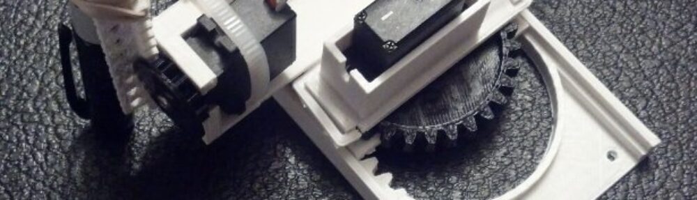

Tiny CNC – all the parts needed
UPDATE: Here’s everything you need to to build a Tiny 3-Axis CNC robot using just 8 plastic pieces.
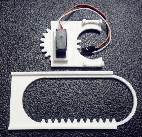
The above are nearly all the tools and parts you’ll need to build your own itty bitty CNC drawing robot. ((You’ll also need an Arduino and some bits of wire)) If you have a 3D printer and a spare Arduino, the rest of the parts should cost you around $20. Right now this robot only has two axes, but in the very near future I hope to add either a Z axis or a pen lift. Without further ado the tools needed are:
Tools
- One small precision screwdriver
Parts
- 2x Micro Servo Motors
- 6x 3D printed parts, downloaded from Thingiverse
- 1x rubber band
- 1x pencil
You’ll also need an Arduino, some wire to connect your servos to the Arduino, and a USB cable to communicate with the Arduino.
Assembly
Step 1: Print parts
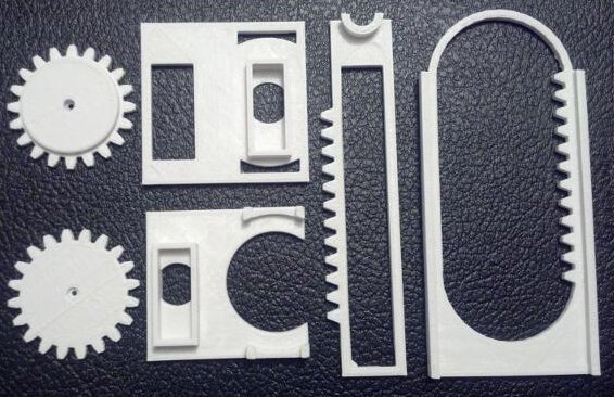
All printed parts
There are only six printed parts necessary for this mini-CNC. If you’re careful, you’ll be able to fit all six on your MakerBot Replicator into a single build plate.
Step 2: Assemble the X axis stage
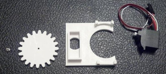
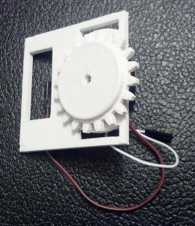
Grab your Micro Servo, the little screw that came with it, the flat gear (really, pinion), and the X axis stage. Just insert the Micro Servo into the X axis stage (it only fits one way), push the gear onto the Micro Servo’s motor shaft, and use the screw to secure the gear. It should look like this when done:
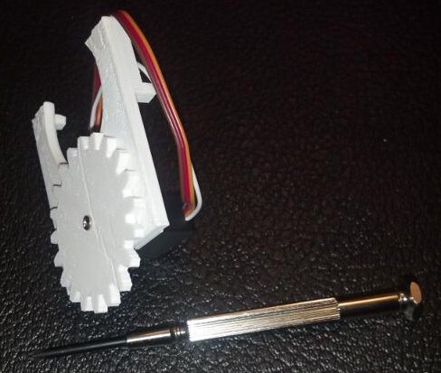
Assembled X axis stage
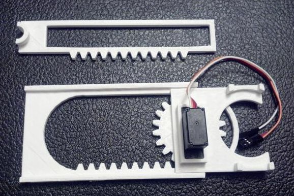
Step 3: Place the X axis stage on the large X axis rack
X axis stage and X axis rack
With the X axis stage gear-side down, rotate the gear clockwise until it stops.

X axis stage and X axis rack
Then place the gear into the X axis rack as show.
Step 4: Place the Y axis rack
Y axis rack
Locate the Y axis rack and place it over the X axis Servo Motor.
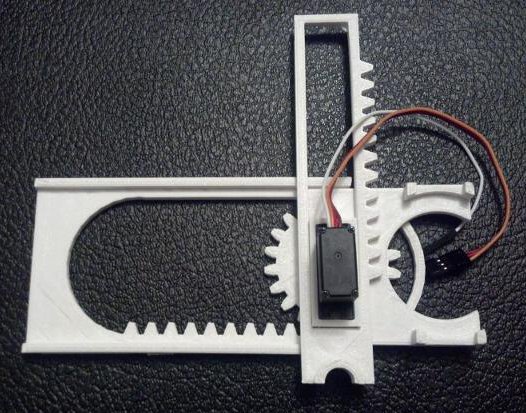
Y axis rack in place
Like so.
Step 5: Assemble the Y axis stage
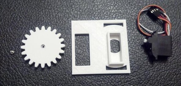
Building the Y axis stage
Just as with the X axis, gather the parts and assemble. This time, the servo motor goes into the stage (it only fits one way), the thick gear is then pushed onto the motor shaft with the gears toward the Y axis stage.
Assembled Y axis stage
Like so.
Step 6: Add the Y axis stage
With the Y axis stage gear-side down, rotate the gear clockwise until it stops.

Getting the Y axis stage ready
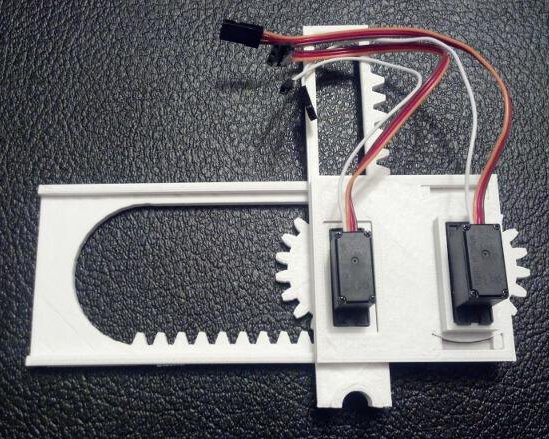
Route the X axis servo motor wires through the rectangular hole in the Y axis stage.
Routing X axis servo motor wires through the Y axis stage
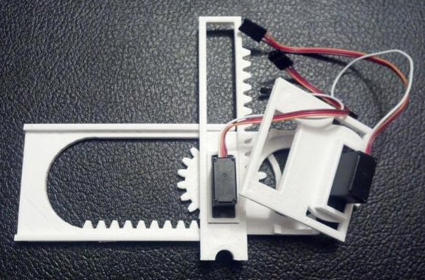
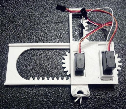
Place the Y axis stage down, with the large rectangular hole around the X axis motor.
Almost done building a robot!
Almost done!
Step 7: Ready the pen holder
Place the rubber band around the pen holder as shown. You will probably have to wrap it around a few times.
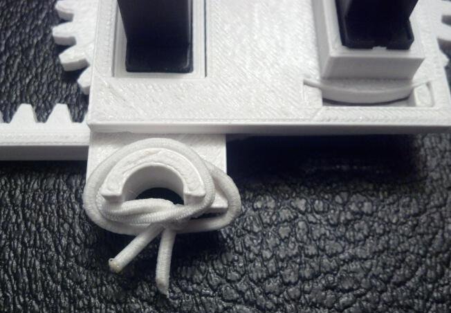
Rubber band wrapped pen holder
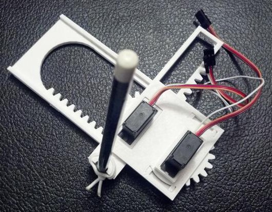
Insert a pencil, pointy-bit down, into the pen holder.
Full assembled drawing robot
Step 8: Admire your work
A baby robot is born!
Your robot is done!
Step 9: Wire Robot to Arduino
To save you a little bit of trouble reading the Arduino sketch and figuring it out, here’s how you would connect your robot to the Arduino:
- Use a piece of wire to connect the orange wire from the bottom X axis servo to pin 13 on the Arduino
- Use a piece of wire to connect the orange wire from the top Y axis servo to pin 12 on the Arduino
- Connect the brown wires from the servos to the ground pins on the Arduino
- Connect the red wires from the servos to the 5v pin on the Arduino
Step 10: Draw!
Download my Arduino sketch to operate this robot. The movements of the robot are hardcoded at the moment, so please check back for updates. Also, if you don’t tape or glue or somehow affix the little bot to a heavy surface, it will literally jerk itself all around the table. (Although, in retrospect, I could have made it draw slower…)
It’s a little difficult to see the lines as the robot is drawing, but it really is drawing a grid in this short video:
Room for Improvement
I hacked this little project together just in time for the MAKE and GE Robot Hacks presentation on 11/20/2013, so I know there’s lots of room for improvement. Here are some things I’m working on:
- An entire Z axis or pen lift mechanism using a third servo
- A better pen/pencil holder
- Actual code to use XY coordinates instead of directly specifying the degrees for each servo
- Actual motion control software from Processing or Python
- A few adjustments to the Y axis stage for a better fit
- Possibly thicker gears so that I can use set screws
- A variation on the gears to use less plastic
- Getting the robot to work with my Adafruit Trinket!
I hope you enjoyed this quick to print and easy to use desktop drawing CNC!
Default Series Title
Pingback: A Six Part CNC Machine
I’d like to see version 2.0.
@Stan: In that case, check back in a few days! Better yet, join my mailing list ( http://shor.tw/x6 ) and I’ll let you know when it’s ready…
Hi,
Is this a mailing list or a new letter? When I try to register it looks like a news letter. I am interested in the project as I have been trying to make cheap printers/plotters for a while.
Your design looks very elegant. I have been following a slightly different approach by also using lego blocks but this is a really a nice project.
@keesj: I’m honestly not sure about the difference. You sign up, leave your email address, and I email people once in a while with updates – on average probably once a month. Lately it’s been a little more as I’ve been extra inspired. 🙂
The difference between a mailing list and a news letter is that the latter is one way only, and a mailing list is like a forum over email, where every subscriber can participate.
@Jelle: Ah! Okay, then it is newsletter. 🙂
Definitely going to make one of these!
Quick upgrade:
1. Remove pencil
2. Replace with roller-ball or felt-tip pen
3. Upgraded visibility of drawing!
@GeekDoc: Well, then, you should have checked out this post! http://plotterbot.com/2013/11/better-video-of-tiny-cnc-drawing-robot-actually-drawing/
Pingback: Miniature Servo-controlled plotter | RaspberryPiKitchen
Pingback: One set of Tiny CNC plastic parts up for grabs for $0.05 | PlotterBot
Pingback: How to Build a Tiny CNC Drawing Robot « adafruit industries blog
Pingback: Links: November 25 | Visual Art & Technology
Pingback: Hacedores – Haz un pequeña CNC dibujante
For the love of God, can we please hold our cameras sideways?
@Chris: I was holding it sideways… it’s just that I was born with my head attached 90 degrees to my neck…
What a nice little project! We´re printing it now but we discovered that not all micro servos are created equal: ours don’t fit (Modelcraft MC-1811)! The axle is not centered in the X/Y axis stage and it sits too deep. What is the brand/type/model/part number of the micro servos you are using?
@Fabsterdam: Oh no! I know that there’s an error in the Y stage STL which causes the motor to sit slightly too deep. This is already fixed in a version I’m part way done on. I’m using micro servos named, “Batan B2122” but I think these from Adafruit would probably work.
Would these work?
http://www.amazon.co.uk/gp/aw/d/B00DAN8XI0/ref=mp_s_a_1_1?qid=1387747316&sr=8-1&pi=SL75
@Andrico: Maybe! I know others have used my designs with those exact motors for a working robot. Even if it’s a loose fit, you should be able to make it work with a little bit of hot glue.
Pingback: Community Corner: Tiny CNC Drawing Robots, NeoPixel Snake Game, a Retro Admiral Set RasP XBMC Rig, and other Projects from this Past Week in Adafruit’s Community « adafruit industries blog
Um, where is the arduino sketch. The above link just leads you to the thingiverse page. I’ve printed it out, it needs a brain! Thanks.
@Ian: I uploaded it to the Thingiverse page too!
I can’t find the arduino code either. Even on the thingiverse page? Can you provide link?
@Haiyan: It’s still there on the Thingiverse page with the printable files! Click “Download This Thing!” and then the file named “MiniCNC003.ino” or “Download All Files”
Pingback: 3D printable drawing bot – Mini CNC | printing3dmodel
First off, this is a brilliant project! Thanks for sharing it. I have an 11 grade student who is really into it, has printed out the 3-axis plotter and I’ve just gotten the motors for her to put it together. She plans to make a button controller to draw with it.
Second, I want to give a rundown on what worked and such:
*Printing all parts of the 3-axis plotter in PLA was successful. Worked on the first print.
*I ordered the micros from Adafruit you mentioned above, http://www.adafruit.com/products/169, they fit perfectly.
*I assembled the pieces myself with the motors and found only one slight problem. In step 4 where you “pressure fit the Y motor mount onto the X axis” I had to do some filing before it would begin to fit. It’s very tight. I guess that’s important to hold it in place, but you might want to suggest having a file on hand.
Again, excellent project!!!
@Erik,
Thank you! I’m glad to hear you guys were able to get yours working. I love the idea of making a button controller for this robot. Doing so means it could be operated without the need of a computer. I was thinking about using my Makey Makey, with its integrated “directional keypad” to directly control the robot.
I’m particularly glad to hear your parts came out well in PLA. I’ve only printed my versions in ABS to date.
I actually designed this robot and the motor mounts with Adafruit’s analog micro servos (totally overkill for this project – but they’re what I had on hand) which probably explains why your parts needed a little extra sanding/filing. With the next version of these parts and the associated assembly guide, I will be sure to include a mention of sandpaper/file. 🙂
Please send me a picture or upload one to the Thingiverse page – I’d love to brag about your success!
@MakerBlock, it turned out the Z axis pinion needed sanding the diameter down almost to the gear teeth to get the Z rack to fit without pushing the Z pinion and servo away at a tilt. I can’t see how you got yours to fit without doing that. I will definitely upload a picture, it looks awesome. Just still working on attaching a pencil securely. Also, this is an awkward place to post code, but this Arduino sketch is a quick way to determine your min and max positions for each servo people might find useful. It does not use a motor shield, just the standard Servo library:
//Just for testing initial servo positions of 3-axis plotter by @MakerBlock
#include
Servo myservoX;
Servo myservoY;
Servo myservoZ;
int posX = 180; //X = 180, in position (not out)
int posY = 0; //Y = 0, right position seen from behind
int posZ = 0; //Z = 0, up position
void setup()
{
myservoX.attach(3); // servo on PINOUT 3
myservoY.attach(4); // servo on PINOUT 4
myservoZ.attach(5); //servo on PINOUT 5
//init positions
myservoX.write(posX);
myservoY.write(posY);
myservoZ.write(posZ);
}
void loop() {
//do nothing
}
@Erik: Oh, yeah, I need to revise that Z pinion. There’s a small error in the code that causes the flange to be too wide. I just forced it together on my robot and it just works. If your code doesn’t show up well in the comments section, I’ll post it in the blog. Have you tried the code I posted on Github? It should let you operate your drawing robot ready to draw SVG files.
Pingback: Links: January 20 | Alexander Russell + Blog
Just saw your mini CNC project….love it!
I’m a Mentalist looking to build a new illusion using this technology. How much smaller can this get?
Jeff
Hi!
Thank you for the tutorial!
I haven’t got 3d printer… but if anybody tell me how size the parts I can make it.
Thank you very much!
Pingback: Miniature Servo-controlled plotter | rPi Kitchen
This is awesome – did you ever finish the z-axis upgrade and post it as well?
@Rusty: I did finish the Z axis upgrade and posted it!
Thank you! I’m looking for a way of creating a hand-operated pretend-CNC machine to help my students understand what the CNC Plasma table is doing. This has helped me figure out some of the parts that I can create to make that happen. Thank you!