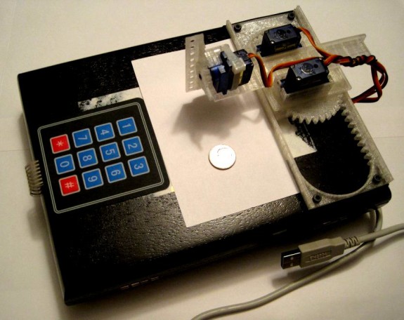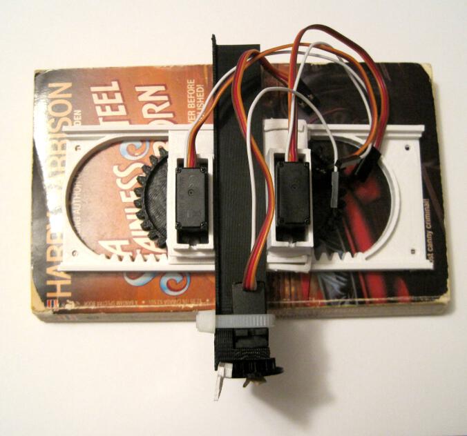
Assembled Tiny 3-Axis CNC Drawing Robot
FYI, if you like drawing robots and want to stay updated, please consider joining my newsletter. Just stuff about drawing robots, no spam.
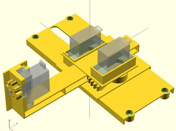
The Tiny 3-Axis CNC robot is a cheap, easy to build, extremely minimalistic but very capable little robot. ((Smaller than a paperback novel!!!)) This is the assembly guide for the version 0.29 robot available for download from Thingiverse. The above picture shows the fully assembled robot. If you have ever put together a lego set or built anything from Ikea, you should be able to build the entire robot in less than 5 minutes. I’ve uploaded step-by-step photographs with each “step” organized into a short slide show of pictures.
This slideshow requires JavaScript.
Here’s everything you need to build your robot.
Stuff You Need
Tools
- One small precision screwdriver
- Scissors and/or wire cutters
Parts
There are eight plastic parts, one rubber band, one zip tie, and three micro servo motors. Once the robot is assembled, you’ll need to wire it up to the microcontroller of your choice. I’ll link to the wiring tutorial at the end of this post.
Assembly
Step 0: Print the plastic parts

All 8 plastic parts
Although you can fit all 8 parts onto the build platform for a MakerBot Replicator 1, you’re probably better off only about half the files at a time. I would suggest printing the five short pieces at once and the three tall pieces together. All the parts together are about 30 grams of plastic and took my printer about 2.5 hours total. I should point out that I incorporated thin little discs onto the corners of the larger STL files. These are only to help the parts adhere to the build platform and fight warping. You should be able to easily peel them off the pieces without any tools.
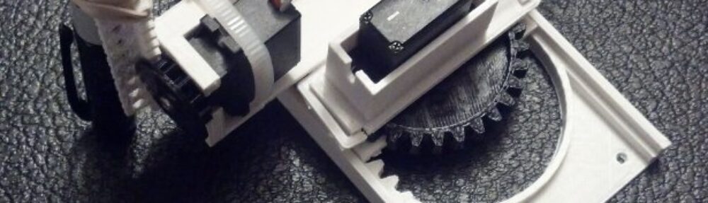
Step 1: Build the Z axis
This slideshow requires JavaScript.
- Gather the parts for the Z axis. You will need three plastic parts (the printed Z pinion (gear), Z rack, and Z motor mount/Y axis), the zip tie, and a rubber band.
- Use the scissors (or wire cutters) to cut a 5-10mm long piece out of the wide rubber band. This piece of rubber band will work as a “gasket” to keep the Z pinion tightly secured to the Z motor shaft.
- Push the screw through the rubber band gasket. Place the Z motor into the motor mount.
- Insert the screw (with gasket) into larger side of the Z pinion. Insert the zip tie into the hole in the Z motor mount and secure the motor in place as show. Try to zip tie your motor in a similar way – if you do it differently the zip tie can hit other moving parts. ((It won’t damage anything, but it will be a nuisance!))
- Cut off the excess zip tie with your wire cutters ((This is where they really come in handy))
- Place the Z rack as shown and secure the Z pinion in place using the precision screwdriver. Rotate the pinion back and forth to make sure the Z pinion is placed well on the Z rack.
- All done!
Step 2: Build the Y axis
This slideshow requires JavaScript.
- Gather the parts for the Y axis. You will need two plastic parts (the printed Y pinion and Y motor mount) and another rubber band gasket.
- Insert motor into motor mount and set screw into the gasket
- Secure the Y pinion onto the Y motor using the set screw and you’re done!
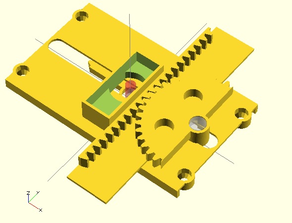
Step 3: Build the X axis
This slideshow requires JavaScript.
- Gather the parts for the X axis. You will need three plastic parts (the printed X pinion, the X motor mount, and the big X rack) and another rubber band gasket.
- Insert motor into motor mount and create another screw-gasket-pinion combo
- Secure X pinion to the X motor using the set screw
- Looking at parts from top, rotate the X pinion counterclockwise until it stops and place it on the X rack as shown. Roll it back and forth to make sure it stops at either end. If it stops in the middle, just pluck it out and move it to where it needs to be.
Step 4: Put it all together!
This slideshow requires JavaScript.
- Gather the Y and Z axes. The Z axis is basically the same part as the Y rack. ((I know, the teeth are a dead giveaway))
- Looking at parts from top, rotate the Y pinion clockwise until it stops. Insert the long flat “fin” on the Y axis through the thin slot in the Z axis. The Y pinion teeth should mesh well with the Y rack. ((AKA Z axis)) Make sure the Z axis is as close to the Y axis as possible. Roll Z axis back and forth to make sure it stops at either end. If it stops in the middle, just reposition the Z axis to where it needs to be.
- Gather the X axis.
- Route the X motor wires through the hole in the Y axis “fin.” ((I really need to think up a better name for that design feature))
- Pressure fit the YZ axis assembly onto the X axis. Make sure the Y axis isn’t too tight on the X pinion.
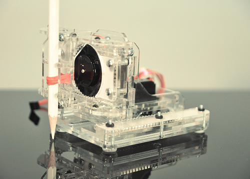
Step 5: Add something to the Z axis
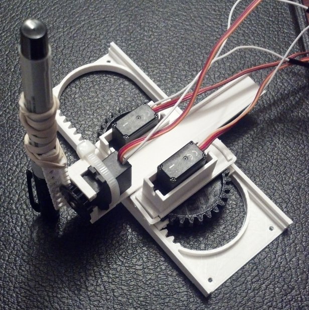
Pen secured to Z axis with rubber band
This Tiny 3-Axis CNC is designed to be a platform for you to turn into anything you want. Personally, I think it would be most fun as a tiny drawing robot. If that’s your interest too, you could use a rubber band or zip ties to secure a pen to the Z rack. However, there’s no reason you couldn’t use it to perform any number of tasks. A fully functional Z axis allows the little robot to actually apply pressure to the drawing surface – making crayon drawings feasible, painting with brushes, some kind of automatic pin-pricking machine, or a gentle tickling robot. By adding a fourth servo motor you could add a robotic gripper, automated syringe/plunger/eyedropper, or something else so entirely amazing that no one has thought of it yet.
Step 6: Wire the robot to a brain
If you want to use an Arduino, I’ve already written a guide on how to run your DIY drawing robot to a variety of Arduino boards. However, there’s no reason you couldn’t run this robot from any other kind of microcontroller or computer provided you figure out a way to operate servos with those devices.
Step 7: Program your Tiny CNC drawing robot
Okay, confession time. I don’t have any software to offer you … yet. As I write this post, my first Tiny CNC design isn’t even 30 days old and is being improved upon and changed quickly. Fortunately, at least two other fine persons have already contributed to this area.
Stephen Laporte has written some software to run an XY version of this robot. Additionally, Thingiverse citizen Oliv4945 has created a Gcode interpreter just for the XY version of the Tiny CNC.
Room for Improvement
Even though this design is only a day old as I write this post, I’ve already got lots of ideas on improving it:
- Pen Holder. I want a better Z rack that is specifically designed to work as a pen holder. I will always offer a non-pen-holder version so people can use this robot as a 3-axis CNC to do their ((Very tiny)) bidding.
- More Secure Drawing. A redesign of the X pinion and X rack. Right now the entire XYZ carriage can pop out of the X rack if the robot meets too much resistance. ((RESISTANCE!!! IS!!! USELESS!)) I have an idea to fix this problem completely. If it works, the robot could be bolted mounted vertically or upside down and still work just fine.
- Reducing plastic. Interestingly, I reduced the amount of plastic in the design from version 0.18 to version 0.29 even though I added an entire additional axis. The plastic could be reduced by thinning some parts and adding holes to other parts as The NewHobbyist did. The interesting thing about “holes to reduce plastic” is that the actual “savings” may be illusory. With 3D printed plastic parts adding holes to a design can significantly increase the amount of plastic used – when you’re printing at less than 100% infill. As a thought experiment, think of two plastic cubes with a 1mm thick wall around all surfaces. One plastic cube has no holes and is printed at 10% infill. The second plastic cube is also printed at 10% infill – but because it is riddled with holes that require a 1mm wall around every hole, there is basically no space for the 10% infill. The “holes to reduce plastic” trick only works on 3D printed parts that are thin pieces. When it comes to parts that are injection molded, it’s my understanding that additional “holes” all the way through a part adds to the design complexity and can increase tooling costs. That said, it would actually result in a reduction of plastic in a design.
- Electronics. For a variety of reasons, there isn’t one particular electronics/microcontroller solution that strikes me as the “best.” ((That said, the Adafruit Trinket is ALMOST perfect for this job!)) For this reason I’ve considered possibly designing a tiny Arduino board with three or four servo pin-outs specifically for this robot.
- Software. I have some ideas on this and a heck of a headstart from Stephen and Oliv4945. 🙂
- AFRON UAER Challenge. If you haven’t heard about it, African Robotics Network (AFRON) has a new Ultra Affordable Educational Robot (UAER) design challenge this year. They’ve also extended the submission time for the 2013 challenge to January 15, 2014. With some creative sourcing and scrounging, I think I could bring the “cost” of this robot down to $10-$20. This is a somewhat artificial goal since the “cost” as far as the UAER does not include shipping, taxes, tools, packaging, computing, and is based on the proportional cost of bulk-pricing. I think I could enter this robot into the hardware, software, and community challenges. I don’t have enough experience designing educational curriculum to outline the 20+ hours worth of material necessary to enter the curriculum category of the challenge.
If you’ve enjoyed this post, perhaps you’d consider donating a +1 to my WyoLum Innovation Grant challenge entry. 🙂
Default Series Title