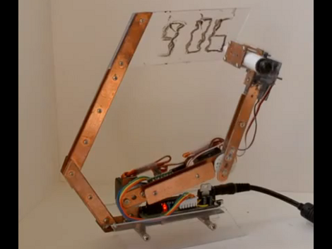

Mirobot, ready for drawing!
A few weeks ago I stumbled across the Mirobot website after seeing a post on the Arduino forums. The creator, Ben Pirt, designed this cool open source drawing robot that is driven over WiFi to roll around and draw. One of the nifty things about this project is that the robot is that it has an almost unlimited drawing size.1
Ben was kind enough to answer a few questions about his project:
- What is the Mirobot?
- Mirobot is a simple drawing robot that’s designed to help children learn about programming and technology. It’s all open hardware and software so once you’ve done some of the basic exercises and you’ve built up your confidence you can start hacking it to do different things. It’s battery powered and WiFi-enabled which means you can put it on your home network and just start using it from any web enabled device.
- How did you get started in robotics?
- This is my first robot really! Although I guess back in the 80’s was when I first got my hands on a robot when I used the BBC Turtle. I was lucky because my Dad was a teacher and was involved int he early days of computers in schools – I was his willing guinea pig. Every school holiday he would bring something home to play around with and the Turtle was always one of the most popular things.
- Why did you decide to work on a drawing robot? Where there any other robots that inspired you?
- A couple of years ago I took my kids to the Science Museum in London (worth a visit if you ever get a chance) and saw one of the original Turtles that I’d used in my childhood. After being immersed in technology for a while now it struck me that what was then a very expensive and complex machine could now be constructed relatively easily and at low cost. In the era of the original Turtles you were lucky if you had one per school, but with an open hardware approach and using open platforms like the Arduino, much of the development is already done. I’m now able to build a robot that improves on the original (it has batteries, uses WiFi) at a fraction of the cost.
- But the real reason I decided to start work on the project was so that I could build it with my kids. We built the first release over Christmas and it’s evolved from the learning that gave me.
- Who do you see using these robots? What do you hope they’ll learn as they build and program the robot?
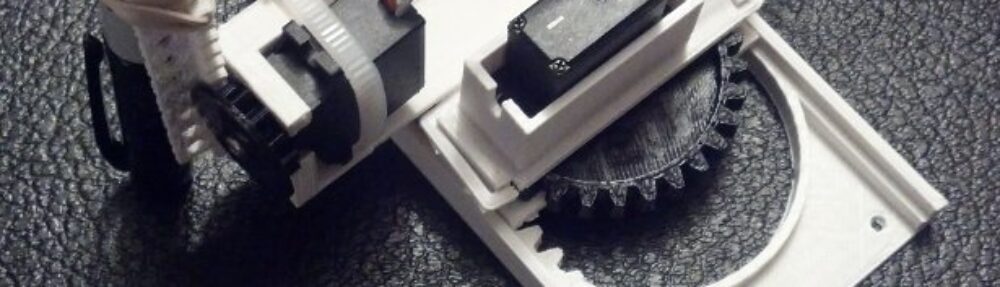
- It’s designed with children in mind – it’s been made easy to assemble and I’ve put a lot of time into making sure the PCB is easy to solder. I’m hoping to work with schools so that a class can all build their own robots and then start learning by using them. When you build the robot yourself you have a much greater appreciation of where it came from. As you put together the PCB I take the opportunity to explain what each piece is doing so even if you don’t fully understand how it works, you still get more of an understanding about what it’s doing. You also get more of a mechanical understanding about how things fit together because nothing is hidden and you can see what everything is doing. Once you start using it you can obviously develop your understanding of some basic programming, but once you’ve mastered this there are lots of other ways you can learn by modifying it;
- – you can customise the web application and learn Javascript / HTML
- – you can program it from Javascript, either in-browser or via Node.js
- – you can modify the firmware and add functionality to the robot
- – you can add sensors to develop what it’s capable of
- It’s designed with children in mind – it’s been made easy to assemble and I’ve put a lot of time into making sure the PCB is easy to solder. I’m hoping to work with schools so that a class can all build their own robots and then start learning by using them. When you build the robot yourself you have a much greater appreciation of where it came from. As you put together the PCB I take the opportunity to explain what each piece is doing so even if you don’t fully understand how it works, you still get more of an understanding about what it’s doing. You also get more of a mechanical understanding about how things fit together because nothing is hidden and you can see what everything is doing. Once you start using it you can obviously develop your understanding of some basic programming, but once you’ve mastered this there are lots of other ways you can learn by modifying it;
- How big a drawing is the robot capable of? How complex a drawing?
- Well the robot is battery powered and wireless so the question is how big is your piece of paper? I do have some plans to make a massive drawing at some time!
- Besides drawing what else could people do with this robot? Do you think there are any commercial or industrial applications?
- I definitely see Mirobot as a base for future experimentation so I can see people adding sensors and making it autonomous. Maybe someone will use it as a base to make the cleaning robots like in the Fifth Element! I’ve intentionally brought out any unused pins on the Arduino to a header so that it’s easy to add hardware.
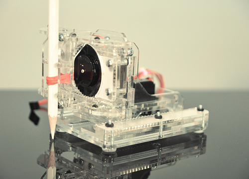
- Why did you choose to go with a custom designed board rather than an Arduino with a motor shield? What other applications do you see for the Mirobot board?
- I originally started with a shield for a regular Arduino but found that it turned out to be quite expensive (and one of the goals of the project is to make it as low cost as possible) and also quite bulky. It began to impact on the physical design of the chassis and was quite difficult to mount (it required screws, and these cost money and add to the complexity of the construction process). I also wanted people to be able to completely build their own robot so liked the idea that you really do build everything. By building a custom board I can make it fit perfectly into the design of the robot.
- Why did you choose open source?
- I’m a big believer in the Open Source approach and I think this is the perfect project for it. If the aim of this project is to get it into as many children’s hands as possible then allowing anyone to make it, and also to learn from the making process, is a key part of that.
- What’s your favorite thing to draw with the Mirobot?
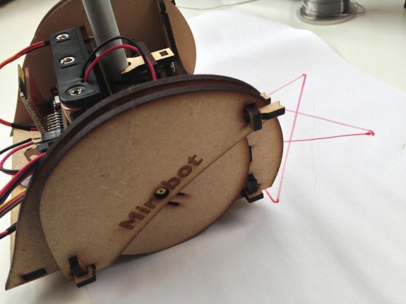
- At the moment my favourite test pattern is the classic 5 pointed star which can be nicely drawn in LOGO by doing:
- repeat 5 [
- forward 100
- right 144
- ]
- Although I’m still learning! I’d like to teach it to do some portraits by converting vector images to drawing commands.
- At the moment my favourite test pattern is the classic 5 pointed star which can be nicely drawn in LOGO by doing:
Thank you to Ben for taking the time to share more about his project!
Mirobot – drawing!
”Plotter
- As long as the paper, pen, and batteries hold out! [↩]