Linus the Artistic Robot by PixelatedThoughts

Linus the Artistic Robot

Linus the Artistic Robot

I’ve always intended that this website be about more than just the few robots that I’ve built.  It’s also about other robots that perform art, especially those that draw.  I’m hoping to make these kinds of “plotter profiles” a more regular thing on this blog.

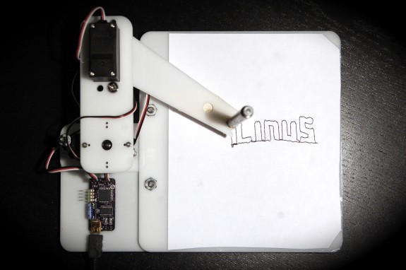
Every once in a while I do a search on Kickstarter just for drawing robots.  Last week I happened upon Linus – a simple drawing robot which uses open source software.  With only a few days to go on the campaign, I reached out to the creator Jacob Balthazor of PixelatedThoughts.com and asked him a few questions.

  • Why a drawing robot? Were you inspired by any other project in developing your robot?
  • I guess I was attracted to the poetic irony of a robot; a word we attribute with being mechanical, orderly and blind to creativity, that can create a piece of art in the very human way of dragging a pen across paper. I am working on some software to take this idea further. The program would make Linus randomly grab a picture off of the internet and interpretively draw it daily. This way you would always have a new piece of art every day, freeing Linus from the creative bounds of the users creativity.
  • Have you used it for anything else other than drawing? What else could you do with this robot?
  • Because of Linus’s simplicity it can be very easy to modify and and even swapping the utensils he hold can lead to vastly different functions. I am very excited about the possibility of using the circuit scribe pens (a pen that can essentially draw a wire) with Linus to draw intricate circuit patterns on paper. I am interested to see what other applications people come up with for Linus.
  • What was the hardest part about designing this robot? Why did you choose to go with a inverse kinematics instead of an XY gantry?
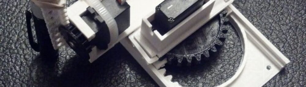
  • The most difficult part of creating Linus was solving the inverse kinematics (difficult non linear geometry problem) math problems to translate the x and y locations that the drawing programs uses to the angles that the robots arm would take to go to those locations on the paper. Tthe mathematical solutions are something that even take a computer a bit of time to compute which is difficult when the robot needs the equations computed fifty times per second. Most other robots are not constructed with arms for this very reason and have mechanisms that move them directly in x and y directions without the need of an equation doing space transformation between. But it was the use of an arm in Linus which allowed us to keep the cost of parts down. Linus would have been less reliable and significantly more expensive if we constructed it with an XY gantry.
  • Why servos instead of steppers?
  • Servos offered a more complete and compact solution. If steppers were used instead, a couple things would have happened with the design. First Linus would have grown in weight and size messing with the small form factor. The weight of the steeper on the suspend second joint could potential cause problems. Because steeper motors without gearing don’t have quite the resolution as servos, a gear system would be needed adding quite a bit of complexity, increasing the price and number of things to fail. The servos allowed for great resolution, and ultimately kept the design elegant and less expensive to produce.
  • What is the drawing area?
  • The drawing area of Linus is currently 4.5 inches square. But we are working on a way to expand the drawing area potentially to six by six through messing with the inverse kinematics equations and software.

Thanks Jacob!  Good luck with your Kickstarter campaign!

TinyCNC Two steps forward, one step back!

Intermediate version with minor design changes

Intermediate version with minor design changes

Above is a picture of the most recent version of this robot.  It includes two nifty changes and one design aspect1 that will probably involve me using design elements I had discarded earlier.  Here’s what I’m working on:

  1. No tools.
    1. The problem with using set screws to affix printed gears to the servos is that too little tightening means the gears will slip2 and too much tightening will strip the micro servo gears almost without warning.3 I’ve redesigned the pinions (gears) so that you can just push the servo horn through the gear and then push it onto the servo gear.  If you wish, for smoother and more reliable operation, you can always add the servo set screw to the servo horn, but it isn’t necessary. Best of all, you’re not going to strip your micro servo gears when you do this.
    2. This design did not come without concession.  I had to compromise on my ideal of removing overhangs.  All published parts to date have been printable with completely flat bases and without even slight overhangs to improve and ease printability.  In order to create the smaller pinion above, I had to add an overhang.  However, it’s a short overhang, which should still easy enough for most printers.
  2. Redesigned motor mounts.  I’ve changed the motor mounts so the fit the4 micro servo motors I purchased.  Hopefully they’ll fit yours too.  🙂  
  3. Improving the X axis.
    1. I’m reasonably happy with the X axis.  It’s not idea – but it works.  I’m designing a way to invert the X rack, so it is trapped by the X pinion and the entire robot can stay together.  This is still in an early design stage and so far requires lots of other design changes, so I’m trying to solve the Z axis and Y axis problems before working my way out to a better X axis.
  4. Improving the Y axis.  
    1. The problem.  The Y axis I created for the version 0.29 steady as the the Y axis in the version 0.18.  With the earlier version the Y axis slid on either side of the X motor mount, so that it was difficult for it to wobble side-to-side.  The newer version only slides along one side and incorporates this a long “fin” intended to stabilize the Y axis’ side-to-side motion.  That “fin” also had a long groove in it that was designed to help with up-and-down motion stability.  I think it worked for the most part.  In reality, the Y axis can wobble as much as a 1-2mm to the left and right in the new version.  One of the reasons I moved to the system used in the version 0.29 is that it allowed me to place all the motors in a very compact area while keeping the Y axis relatively short.  This conserved plastic, kept the part sizes small, and kept most of the mass in the robot in one area – which I felt would help reduce wobble.  
    2. The solution?  
      1. One obvious route is to go back to the Y axis alignment system used in version 0.18, where it slid along both sides of the X motor mount.  I moved away from this system because there didn’t seem to be a good way to mount the Z motor.  Not having a really great solution to mounting the Z axis motor isn’t that big a deal.  The current motor configuration is reasonably symmetrical and aesthetically pleasing, but not critical by any means.  As long as the robot isn’t operated at ridiculous speeds, the unsymmetrical motor mounting shouldn’t be that big of a problem.  While I have another design option, I think this is the system I’ll end up using.
      2. The other option is to cut a long groove in the Y axis with a tab sticking out of the X motor mount5 to keep it steady. As the Y axis slides back and forth, it should be kept in line by the tab.  Similar to this, I could also put a groove in the X axis where the Y axis slides to keep the Y axis in line.
  5. Improving the Z axis.
    1. The Z axis is a little wobbly.  While a little wibbly-wobbly-ness is to be expected, when there’s a little introduced with each axis, the effect is compounded in the end result.  This isn’t a problem for large gross manipulations, but becomes more obvious when drawing.  One of the reasons I’m tuning this robot to draw well6 is that if it can draw well, chances are it can do other tasks well too.
  6. Improving the X axis.
    1. I know this isn’t in any obvious order.  🙂  However, I’m reasonably happy with the X axis.  It’s not idea – but it works.  I’m designing a way to invert the X rack, so it is trapped by the X pinion and the entire robot can stay together.  This is still in an early design stage and so far requires lots of other design changes, so
  7. Things to try out.
    1. Drawing without pens.  Recently the idea occurred to me that drawing with a pen may not be ideal.  A pen is designed for the human hand – so it has heft, grip, length, and all sorts of other attributes that aren’t ideal for a robot.  However, the pen cartridge/ink reservoir is shorter and has considerably less mass.  So, why not just pull that out of a pen and scrap everything else?  Heck, there might even be an interesting way to incorporate the pen’s own spring into the design.  I think it would be incredibly interesting to use that spring as the basis for a pen holder.7
    2. Smaller, more numerous teeth.  I honestly don’t know if these are beneficial.  I’m guessing there’s a law of diminishing returns when it comes to using smaller teeth.  Smaller teeth are harder to print and may be easier to break or more prone to skipping.  On the other hand, it is possible they might allow for smoother and more reliable operation.  I’ll try it both ways and let you know!
    3. Closer meshing between pinions and racks.  I’ve designed the robot with a degree of “slop” between the pinion and rack teeth.  This is so that I can make parts that I know will fit and work on many different robots.  I like to think I’ve got my Replicator 1 dialed in pretty well – so it’s entirely possible I could place the teeth closer together.  I figure closer meshing probably involves more stress on the motors, but that’s another problem for another day and another blog post.  😉
    4. Designing with fasteners in mind.  One interesting solution from Joseph is to put zip ties around the various parts to keep them in place.  The zip ties are apparently smooth enough that the parts still slide and stay together.  I love this solution.  I think it could be even better if zip tie solutions were further incorporated into the design as fasteners.
    5. Putting it all together.  The new-ish design you see at the top allows for the use of servo set screws without actually requiring them.  They’ll help, but aren’t critical.
  1. The Y axis []
  2. Even with foam rubber stickers! []
  3. There’s a slightly sickening crunch as you do.  I don’t recommend it []
  4. Many, many []
  5. This makes more sense if you’re inside my head []
  6. As well as can be expected for a bunch of plastic parts and cheap motors []
  7. I’m not sure if this would be cannibalistic or meta.  Thoughts? []

Robot Challenge Marathon

3. Materials required: 8 plastic parts

Eight plastic parts

Whew!  It’s been a wild few weeks!

Just a few weeks ago I found out about WyoLum 2013 Innovation Grant and discovered that the AFRON 2013 Design Challenge had been extended.  I then began a foolish feverish attempt to enter both challenges before their respective deadlines (12/31/2013 for the WyoLum Innovation Grant and 1/15/2014 for the AFRON Ultra Affordable Educational Robot challenge).  I found it difficult to get the robot’s plastic part design and software to an acceptable point for submission for the WyoLum Grant and probably more difficult to get all the documentation in for the AFRON challenge since their challenge required so many parts – pictures, videos, putting on a robot building workshop.

If you’re interested in reading a LOT about the Tiny 3-axis CNC drawing robot, my entry into the AFRON 2013 Design Challenge is here.  Between that page and the software user guide, I’ve written more than 11, 000 words and added 115 pictures and 5 videos.

If there was just one page on this entire site to teach you more than you ever wanted to know about how to build a tiny drawing robot (including what parts you could scavenge, where to find them, what parts you can substitute, how to wire up the robot, program it, and get it drawing) look no further.

Tiny Drawing Robot Gallery

Two R2D2's

Two R2D2’s

This last weekend, when I should have been working, I was having a blast drawing tiny drawings with my tiny drawing robot.  Under the kind and benevolent tutelage of TechNinja, I improved my Arduino and Processing sketches, started a repository for the software/firmware for the Tiny CNC drawing robot, and merged his pull request to add some code to make this little robot compatible with the CNC server software written to run the WaterColorBot and EggBot.

Above are probably the best drawings I’ve managed with my little robot to date.  The drawing is about 2 inches tall.  The one on the left is from a single “pass” of the drawing robot, the second is from the robot drawing the same picture three times in a row.  I was quite surprised that the robot was able to draw the same picture several times and repeat the drawing so well.

An image of a weeping angel is itself a weeping angel

An image of a weeping angel is itself a weeping angel

This drawing, of a weeping angel from Doctor Who, is also about 2 inches tall.  This image wasn’t the best topic to draw – but my daughter specifically requested it.  I found a full color JPG/bitmap picture online, imported it into Inkscape, and converted it into a single-color vector graphic for the robot.

A robot drawn robot turtle

A robot drawn robot turtle

This one is a drawing of a robot turtle, from the game “Robot Turtles.”  I pledged to help support this awesome game on Kickstarter and it arrived a little before Christmas.  While it didn’t get immediate attention on Christmas day, we played the game for the first time a few days later and my daughter loved it.  I think it was really smart to design the game with “unlockables” which give the game a gentle learning curve to start and a challenge later on right when the players start to get complacent.  I pulled the JPG/bitmap image from the Robot Turtles community page, turned it into a two-tone vector image using Inkscape, and fired the drawing robot.

I also tried to draw a Death Star, but it turned out terrible.  The SVG version of the image I found was terrible and the robot drawing was even worse.

Robot Friends: Tiny CNC and the WaterColorBot

Super Awesome Sylvia‘s father, TechNinja was able to get their Tiny CNC working with the same software that runs the super awesome WaterColorBot.  I love that these two drawing robots get along so well, rather than using their powers for evil.

You can find TechNinja’s cncserver code on Github.  My Tiny CNC Arduino and Processing sketches on Github here, but from the video above, it looks like TechNinja’s solution is far superior to my own.  🙂

The Tiniest Drawing Robot Actually Draws!

Tiny Drawing Robot satisfied with itself for having drawn a robot

Tiny Drawing Robot satisfied with itself for having drawn a robot

One of the most asked for features of this tiny drawing robot is that it needs software to actually draw things.  Well, wait no more!  The software to actually draw things is now a reality.  Above is a picture of the little drawing robot acting quite smug after having drawn a little copy of the Make robot.

While I’ve developed a basic “toolpath” to draw things, this is not yet a polished work.  There are lots of little hacks I’ve used to get the robot to work.  I’ll jot down as many as I can here so you can follow along at home if you like.  I anticipate developing a much better system very soon that won’t require as much fiddling.  🙂  For now, you can make your own tiny robot draw by following this rough guide:

  1. Download the TinyCNC-Gcode.ino Arduino sketch from Github and upload it to your Arduino.
    1. The Arduino sketch for the Tiny CNC has some hardcoded “limits” to the X, Y, and Z axes.  I added the limits of my own robot, but your mileage may vary.
    2. The robot treats the left most position with the Y axis totally retracted as the (0,0).  (Well, really, the X minimum and Y minimum position).  Thus, it doesn’t try to draw anything that’s not in the +X,+Y quadrant.
  2. Import or draw a picture in Inkscape.
  3. Export the drawing into Gcode using the MakerBot Unicorn Gcode Plugin by Marty McGuire.
    1. Since the plugin treats the center of the drawing as the coordinate (0,0), you’ll need to put your drawing in the top right quadrant of the picture.  I used a drawing area that was twice the height and width of my robot’s drawing area, so that the top right quadrant would be equal to the drawing area.
    2. It’s important to “break apart” the SVG drawing before you try to export the image to Gcode.  If you don’t you’ll probably end up with an error message and an empty Gcode file.
    3. Interestingly, since Marty’s Gcode plugin is written in Python and Python can communicate over USB with an Arduino, there’s no reason you couldn’t make the robot draw something directly from Inkscape.  Wouldn’t that be nifty?!
  4. Download the SendingSerial003.pde Processing sketch from Github and save it in your sketch folder.
    1. Ideally, the Processing sketch would send a Gcode command, wait for the robot to perform the action and then respond saying it was ready for the next command.  I just wanted something that works, so the Processing sketch just waits 1000 miliseconds between commands.  It’s a hack, but it’s a hack that seems to work well enough for now.
  5. Rename your Gcode file to “file.gcode” and place it in the same folder as the Processing sketch
    1. You could just change the filename in the Processing sketch too.
  6. Open the Processing and run the sketch
  7. The robot should leap into action drawing your design!

Here’s a photograph of just the drawing itself:

Make Robot, drawn with a robot made from Make and Adafruit parts, printed on a MakerBot

Make Robot, drawn with a robot made from Make and Adafruit parts, printed on a MakerBot

As you can tell, I haven’t spent a lot of time tuning my robot.  I know it is capable of smoother, more accurate drawing.  These are all things I’m hoping to improve with the next iteration of the design of the plastic parts.

If you’re interested in learning more about drawing robots, you might enjoy joining my mailing list about drawing robots.  No spam, just emails about drawing robots.  🙂