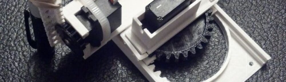
Tiny Drawing Robot satisfied with itself for having drawn a robot
One of the most asked for features of this tiny drawing robot is that it needs software to actually draw things. Well, wait no more! The software to actually draw things is now a reality. Above is a picture of the little drawing robot acting quite smug after having drawn a little copy of the Make robot.
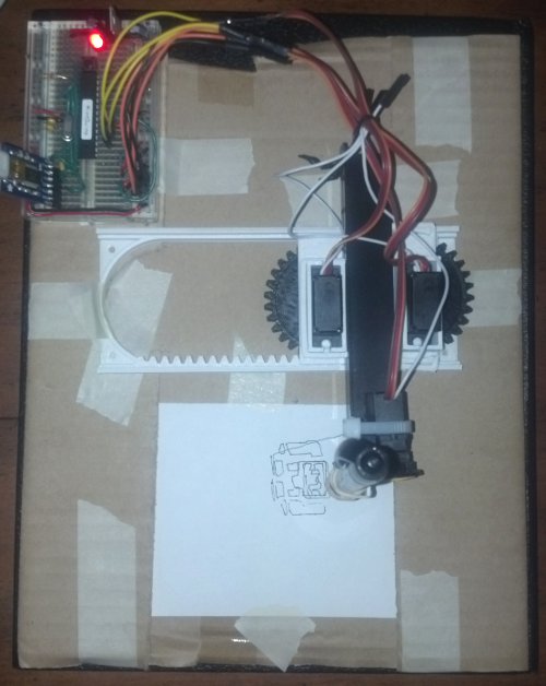
While I’ve developed a basic “toolpath” to draw things, this is not yet a polished work. There are lots of little hacks I’ve used to get the robot to work. I’ll jot down as many as I can here so you can follow along at home if you like. I anticipate developing a much better system very soon that won’t require as much fiddling. 🙂 For now, you can make your own tiny robot draw by following this rough guide:
- Download the TinyCNC-Gcode.ino Arduino sketch from Github and upload it to your Arduino.
- The Arduino sketch for the Tiny CNC has some hardcoded “limits” to the X, Y, and Z axes. I added the limits of my own robot, but your mileage may vary.
- The robot treats the left most position with the Y axis totally retracted as the (0,0). (Well, really, the X minimum and Y minimum position). Thus, it doesn’t try to draw anything that’s not in the +X,+Y quadrant.
- Import or draw a picture in Inkscape.
- Export the drawing into Gcode using the MakerBot Unicorn Gcode Plugin by Marty McGuire.
- Since the plugin treats the center of the drawing as the coordinate (0,0), you’ll need to put your drawing in the top right quadrant of the picture. I used a drawing area that was twice the height and width of my robot’s drawing area, so that the top right quadrant would be equal to the drawing area.
- It’s important to “break apart” the SVG drawing before you try to export the image to Gcode. If you don’t you’ll probably end up with an error message and an empty Gcode file.
- Interestingly, since Marty’s Gcode plugin is written in Python and Python can communicate over USB with an Arduino, there’s no reason you couldn’t make the robot draw something directly from Inkscape. Wouldn’t that be nifty?!
- Download the SendingSerial003.pde Processing sketch from Github and save it in your sketch folder.
- Ideally, the Processing sketch would send a Gcode command, wait for the robot to perform the action and then respond saying it was ready for the next command. I just wanted something that works, so the Processing sketch just waits 1000 miliseconds between commands. It’s a hack, but it’s a hack that seems to work well enough for now.
- Rename your Gcode file to “file.gcode” and place it in the same folder as the Processing sketch
- You could just change the filename in the Processing sketch too.
- Open the Processing and run the sketch
- The robot should leap into action drawing your design!
Here’s a photograph of just the drawing itself:
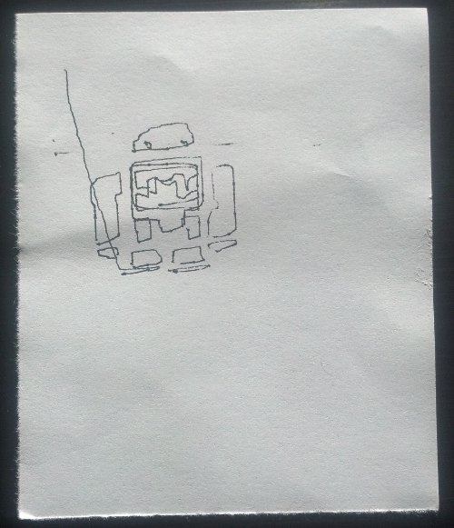
Make Robot, drawn with a robot made from Make and Adafruit parts, printed on a MakerBot
As you can tell, I haven’t spent a lot of time tuning my robot. I know it is capable of smoother, more accurate drawing. These are all things I’m hoping to improve with the next iteration of the design of the plastic parts.
If you’re interested in learning more about drawing robots, you might enjoy joining my mailing list about drawing robots. No spam, just emails about drawing robots. 🙂
Default Series Title