TinyCNC – Working Keypad UI

If you’re still on the fence about trying to build your own drawing robot/plotterbot, take heart.  (Skip to the bottom of the post if you want to check out the latest 3D printable files and Arduino code.)  If a relative newbie such as myself can make a go of it, I’m pretty sure you can too.

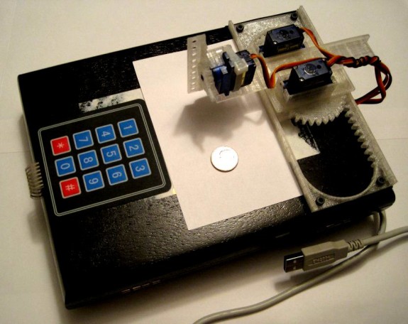
Last night1 I finally got the little ‘bot to really make use of the keypad as a modest user interface.  The robot is now using the USB cable purely for power purposes, rather than requiring the serial connection to the Arduino serial monitor as well drawing power from the USB port.  Now I can just connect the USB cable to a random USB charging device and operate the robot in a meaningful way by using the keypad.

In addition to the keypad direction system described in a previous post, now the “*” and “#” keys also have a usage.  The “*” key now starts and stops the Arduino from logging the inputs.2 Pressing the “#” key will play the most recently recorded inputs.

My record/playback system is super hacky and the ‘bot sometimes jitters before carrying out a command.  I’ll also have to implement a few additional changes to the design of Y axis before it can hold a pen reasonably stead.

But, it works!

Download the latest stable 3D printable parts on Thingiverse, latest Arduino sketch from Github, and play with one for yourself!

  1. Well, technically this morning? []
  2. If you forget whether it has been toggled to start or stop recording, the robot performs a little “wave” with the Z axis when it is ready to start recording and three little “waves” when it stops recording. []

Drawing Robot In A Box

Draw on the go with a small Arduino-powered CNC robot!

Draw on the go with a small Arduino-powered CNC robot!

Well, technically, ON a box.

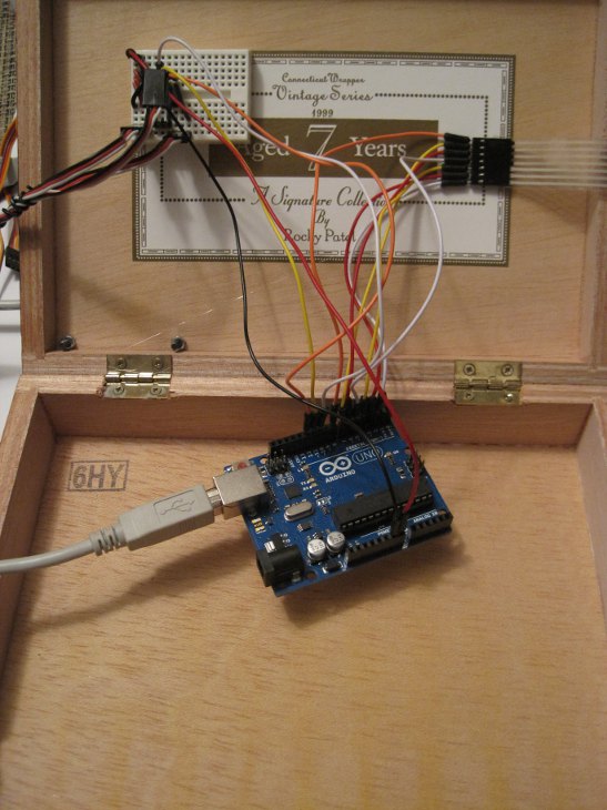
The wiring is really simple.  A small breadboard is used connect Arduino pins 10, 11, 12, power and ground to the three servos.  The keypad is wired directly to pins 2 – 8 on the Arduino.  That’s it.

Wait... that's all there is to it?!?

Wait… that’s all there is to it?!?

Of course, it doesn’t work.  Yet.  🙂

How to Wire a Tiny CNC

Easier than this to wire up

Easier than this to wire up

Don’t you just hate it when you read an online tutorial shows you how to build something – but totally glosses over how to wire it up?1 Me too.  Fortunately for you, dear reader, I’m not going to let that happen to you.  Not today, my friend, NOT TODAY.

The Basics

A few weeks ago I knew next to nothing about how to do anything with an Arduino and least of all how to wire one up.  Even though people had told me it was easy, I couldn’t make much sense of Arduinos except to load sketches I had downloaded.  Here’s some of the stuff I would loved to have known:

  1. Arduinos have a bunch of “pins” that can act as either inputs or outputs.
  2. When you program the Arduino, you tell it whether a pin is supposed to be an input or output.
  3. When the Arduino uses a pin as an “output” it can send a little bit of power to that pin.  That’s enough power to run an LED and maybe a small motor, but not enough to do a whole lot.  For things that require more power, you have to get it power from elsewhere.
  4. Arduinos have little “power regulators” that take power up to 12v and bring it down to 5v so the Arduino can use it without getting crispy.
  5. You can tap into that 5v power line to use for the things that require more power than the output pins provide – but if the things you connect to the 5v power line draws too much power, it can make the power regulator get… crispy.  🙂

Okay – that should be enough to get us started!

Wiring the Tiny CNC to a Mintduino

The easiest “out of the box” solution for wiring the Tiny CNC is with a Mintduino.  The Tiny CNC has two (soon to be three) servos that have three wires – a positive wire, a ground wire, and a control wire.  Each of the servos will need to have power sent to the positive wire, the ground wire grounded, and the control wire connected to an output pin on the Mintduino.  The reason the Mintduino is the easiest solution is it has a breadboard which is a very simple way to connect all the servos’ wires without a lot of fuss.

Here’s how we do it:

This slideshow requires JavaScript.

  1. Build the Mintduino.
  2. Bring power from the programming pins to the board.  Use a piece of red wire to connect the red positive rail to “a28.”  Now when you connect the FTDI Friend to the Mintduino, it will be ble ot draw power from the USB cable.
  3. Add two 3-pin male headers to the breadboard – one on “i23, i24, i25” and one on “i26, i27, i28.”
  4. Using a red wire connect 5v power from the red positive rail to “i24” and “i27.”
  5. Using a black wire connect the ground rail to “i25” and “i28.”
  6. Connect the Arduino output pins of your choice (I used 12 and 13 here) to “i23” and “i26.”
  7. Connect one servo to “i23, i24, i25” with the brown ground wire connected to “i25,” center red positive wire connected to “i25,” and the orange control wire to “i24.”
  8. Connect the second servo to “i26, i27, i28” with the brown ground wire connected to “i28,” center red positive wire connected to “i27,” and the orange control wire to “i26.”
  9. Connect the FTDI Friend to the Mintduino with the USB port side facing the connectors for the servo.

Wiring the Tiny CNC to an Adafruit Trinket

The basic setup here will look pretty familiar to the breadboard from the Mintduino.  Heck, I’m even using the itty bitty Mintduino breadboard in this example.

This slideshow requires JavaScript.

  1. Add two 5-pin male headers and three 3-pin male headers to the breadboard.
  2. One 5-pin header should be placed from “d4” to “d8” and another from “g4” to “g8.”
  3. One 3-pin header should be placed from “i9” to “i11,” a second from “i13” to “i15,” and a third from “i17” to “i19.”
  4. Use a red wire to bring the power directly from the USB on “g4” to the red positive rail.  Do NOT bring the power from the pin marked “5v” at “g8” because that pin draws the 5v through the Trinket’s power regulator rather than directly from the USB line.
  5. Using red wires bring the 5v power from the red positive rail to the three servos at “i10,” “i14,” and “i18.”
  6. Use a black wire to bring the ground from the Trinket on “c4” over to the black ground rail.
  7. Using black wires to bring the ground from the ground rail to the three servos at “i11,” “i15,” and “i19.”
  8. The Trinket can operate up to three servos from pin 0, pin 1, and pin 2.  Connect pin 0 at “h5” to “j9,” pin 1 at “h6” to “j13,” and pin 2 at “h7” to “j17.”
  9. Now drop the Adafruit Trinket in place as shown and you’re good to go!

Wiring the Tiny CNC to an Arduino Uno

I’ll take the pictures and update this part soon, but wiring the Tiny CNC is pretty easy too – as long as you have a breadboard.  Just follow the steps for the Trinket above, but bring the power from the “Vin” pin to the red positive rail and the ground from one of the “GND” pins to the black ground rail.  This will provide the power and ground for the servos.  Now you need to do is connect three pins (say 11, 12, and 13) to the three control lines for the servo at “j9,” “j13,” and “j17.”

Okay!  That’s it for the wiring!

  1. Photo courtesy of Peter Kaminsky []

Tiny CNC Drawing Robot – Cost Estimate

A really tiny CNC - a work in progress

A really tiny CNC – a work in progress

One of my goals in designing/building this little robot was to make it really cheap and easy to build.  I’d like to think I’m headed in the right direction.

I would estimate the cost of building (a completed version of) this little robot as follows:

  1. 3x Micro Servos at $6/each
  2. 1x Arduino Uno at $30
  3. 30.6g of ABS plastic for roughly $1.53

I’m going to exclude the bits of wire and pen, and estimate the materials cost of this robot at $49.53 which I’ll round up to about $50.00 since I have to design and print a few more plastics parts.  Basically, if you’ve already got a 3D printer, plenty of plastic, and an Arduino lying around, there’s no reason you couldn’t have a similar robot up and running in no time for about $20.

It’s my hope to use my newly won Adafruit Trinket 5v, courtesy of Hackaday and Adafruit1 , it might even be possible to power all three servos off of a single Trinket ($8) and bring the total cost of the project down to around $28 plus little bits of wire and a pen.

Although I give vague building instructions on the Thingiverse page for the parts of this robot, I hope to have an Ikea/Lego style set of instructions ready in the next day or so.  So far there are only 8 parts (including the two servo motors), so even a team of monkeys taking a break from writing Shakespeare could manage to assemble one of these in a few minutes.

  1. Thanks again!!! []

An Itty Bitty Drawing Robot

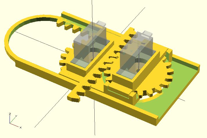
OpenSCAD Rendering of Mini CNC

OpenSCAD Rendering of Mini CNC

My daughter and I recently signed up to take part in Make’s Robot Hacks’ project.  Make was kind enough to send me a box of parts, including the Make Ultimate Microcontroller Pack and a bunch of servos.

The catch?  We had to actually create something and share my progress by November 20.  From the time my parts arrived, this was exactly 14 days.  🙂

I had a number of ideas about what I wanted to make – an automated Robo Hand, electronically released spring loaded wings, a little servo-powered walking robot, and a dozen of other smaller ideas.  My daughter’s ideas were significantly more ambitious – flying, wall crawling, dancing, hearing, seeing, talking, thinking robots.12 The idea that I kept coming back to was a tiny little CNC robot using servos powered by an Arduino – something I had first seen in February of 2012 with Piccolo – the tiny CNC-bot by the Diatom Studio team.

My adventures building robots aside, I still consider myself a “newb.”  However, I knew the basics of what I needed to accomplish:

  1. Drive three servos with a single Arduino
  2. Make each servo drive an axis of movement
  3. Figure out a way to translate 180 degrees into linear movement

So, for what it’s worth, here’s my process:

Driving Multiple Servos with a Single Arduino

Since I had never (!) driven a servo with an Arduino, I needed to figure out how to manipulate at three servos at the same time.  Fortunately, the Arduino “Sweep” example explicitly states that it’s capable of controlling eight servos.

Connecting them was significantly simpler than I was anticipating.  For the Batan B2122 servos I had, the brown wire was ground, orange wire was positive, and yellow wire was the “control” that would have to be connected to one of the Arduino’s digital out pins.3 The easiest way for me to wire up the three servos was through a small breadboard.

Once the servos were wired up, it was a matter of loading up the Sweep example and driving a single servo back and forth.  By adding a few lines, I was able to drive two servos, and then three.

Using a Micro Servo Motor to Drive an Axis of Movement

The Batan B2122 micro servos are not continuous rotation motors – they only have a 180 degree range of movement.  Most CNC machines use stepper motors which are strong, fast, precise, and can rotate continuously forwards or backwards.  Servo motors, by contrast, are smaller, cheaper, slower, and unless they are specifically designated as “continuous rotation” have a limited range of movement.

I considered two different ways, each with their own merits, of using a limited range of motion motor to drive an axis of movement.  The first way I considered was using a spool and twine to drive each axis – similar to the Printrbot Simple and WaterColorBot.  This is an excellent and cheap alternative to using expensive precision toothed belts to control movement.  The reason I didn’t use this method is that it would have required a spool for the twine, and some form of rails or metal rods, and of course twine.  My concern is that this would have been a bulky solution for such a small robot.

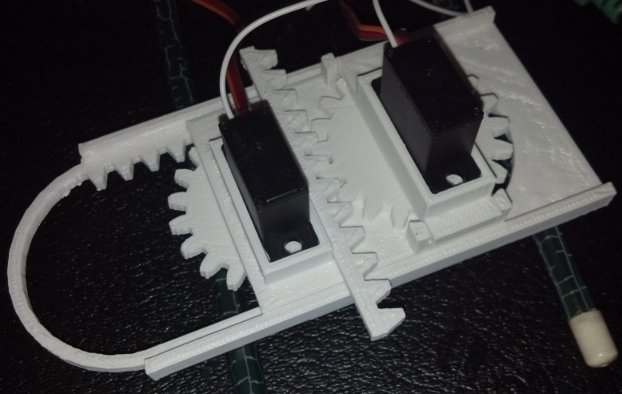
The second method, the one I decided upon, was to use a rack and pinion to turn the rotational motion of the servos into linear motion.  One benefit of using a rack and pinion is that the rack itself removes the need for rails or precision rods, spools, and twine – all while providing a sturdy framework for adding additional axes.

Translating 180 Degrees into Linear Movement

As I alluded to above, the micro servos only have 180 degrees of movement.  Thus, a gear (or pinion) attached to a servo would only be able to drive the rack by 1/2 of its circumference (or 180 degrees).  Keeping that in mind, I chose a gear size that would produce the desired freedom of movement.  I settled on a gear radius of about 20mm because it created about 2.5 inches or 62.8mm [ (2 * π * 20)/2 = 62.8 mm] of movement.

Moving a pen over a 2.5″ square would enable me to create nifty little robo-drawn post-its, bespoke business cards, or an auto-signature device.

Here’s what I have so far:

Next Steps…

Since the robot isn’t actually capable of doing a whole lot yet, I’ve got a bit to do still:

  1. I need software to interpret XY coordinates or GCode into rotational degrees
  2. Get write a Processing or Python script to send the XY coordinate or GCode to the Arduino
  3. Slightly redesign the two gears (well, pinions) so that it’s easier to attach them to the servos
  4. Create a new Y rack that can hold the third servo (for the Z axis) and a pen for drawing

Since I’m only intending to use this little CNC for small drawings, I don’t really need a huge Z axis lift – even a few millimeters should be sufficient.  I was considering cheating a little and just making the “Z axis servo” just lift the front of the robot off the surface.

Even though I’ve got a bit of work ahead of me, I’m pretty happy to have a working proof of concept of a robot of my very own design!

If you would like a little robot like this of your very own, you can find my 3D printable files on Thingiverse and the Arduino code is pretty much the stock “Sweep” example.  Stay tuned because I’m looking forward to turning this into a legit itty-bitty CNC drawing robot.

  1. Just put the words on a microchip and put the microchip in the robot’s head, Daddy []
  2. Thanks pumpkin! []
  3. If this seems like Greek to you, as it did to me just a few weeks ago, I’d recommend picking up a Mintduino kit and blinking a single LED.  You’ll be able to blink two LED’s in no time! []

Building a PlotterBot Arduino Drawing Robot – An Overview

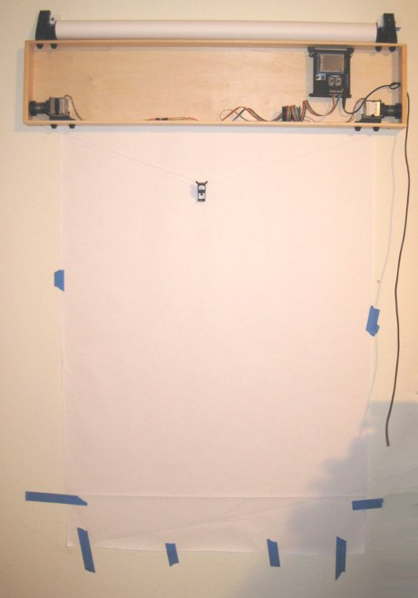
Completed PlotterBot

Completed PlotterBot

A PlotterBot Arduino-based drawing robot is an easy to build robot you can make from off-the-shelf electronics and easily repurposed parts.  At it’s heart, this robot uses a microcontroller to drive motors to reel in and out two spools of wire to move a pen across a vertical surface.  One of the best thing about this particular robot is that it is extremely forgiving.  Your robot will still be capable of drawing huge amazing pictures even if you don’t mount the motors perfectly level, your spools aren’t quite symmetrical, or if your measurements are a little bit off.1

Here’s an overview of what you’ll need to do to build your own PlotterBot:

  1. Parts
    1. 2x Stepper motors
    2. 1x Servo motors (if you want to do pen lifts)
    3. 1x Arduino Uno or greater
    4. 1x Adafruit Motor Shield
    5. USB cable
    6. Power adapter
  2. Hardware and Supplies
    1.  Assorted wire, nuts, bolts, screws
    2. Monofilament fishing line
    3. Solder
    4. A project box or the stuff to build one with
  3. Tools
    1. Soldering iron
    2. Power drill
    3. Screwdrivers, hex wrenches
    4. A 3D printer is very helpful – but not necessary
  4. Assembling the Electronics
    1. Build the Adafruit Motor Shield
    2. Connect the Shield to the Arduino
    3. Load the Polargraph firmware
    4. Connect motors to the shield
    5. Test the assembled electronics
  5. Build the Robot
    1. Connect spools to the stepper motor shafts
    2. Mount the motors in your project box
    3. Wind monofilament fishing line on the spools
    4. Tie the fishing line to your pen holder
  6. Calibrate the Robot
    1. Measure the diameter of the spools and distance between motors
    2. Save your settings and upload your measurements to the robot
  7. Draw
    1. Load pictures into the software and start drawing

Keep in mind that once you have the basics (an Arduino, the shield, and two steppers) you can change the setup to suit your needs.  I’ll discuss more about each of these points, and turning each one into a separate blog post (or more!) soon.

Finally, join the PlotterBot newsletter now so you don’t miss out on the latest information!

  1. Of course, it will do a better job if you get everything right… []