
Tiny CNC – Exploded View
This weekend I’ve been slowly working to improve my Tiny CNC. There are a number of potential mechanical changes that would very likely help with the accuracy, performance, and even reduce the cost of this little robot. Here are some of the things I’m fiddling with so far:
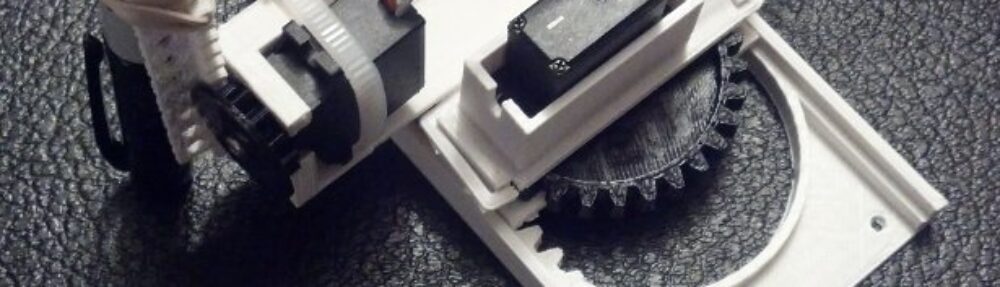
- Herringbone Rack and Pinion
- The reason so many RepRaps use herringbone gears is that they help to reduce backlash, the play between the rack and pinion. The downside to herringbone gears is that they’re difficult to produce – except by 3D printing. Fortunately, since this entire design 3D printable, this is not a problem. As a practical matter, it’s not really any more difficult or time consuming for a 3D printer to create a herringbone gear than it is to create a non-herringbone gear of the same size.
- Since I couldn’t find an easily modifiable OpenSCAD script, I had to write a few modules to create herringbone racks and pinions. My script for the rack is so unbelievably “hacky” that I am actually a little ashamed to admit how I cobbled it together. I’ve also reduced the size of the teeth used to hopefully get finer control. The flip side is that it might make it easier for the ‘bot to accidentally skip a step. We’ll see!
- Drawing Area
- I’ve arbitrarily chosen a 75mm x 75mm square ((2.95″ by 2.95″)) as the necessary drawing area. Why this size? First, it would be difficult to print the parts much larger than this. Secondly, this is just large enough to draw on three different kinds of common materials – traditional American business cards which measure 74mm x 52mm, and Post-It notes which measure 3″ x 3″ or 76mm x 76mm, and 3″ x 5″ rectangular ((76mm x 127mm)) index cards. The versions published to Thingiverse are able to move in the X and Y axes by about 65mm or so – just shy of my desired goal. Thus, I’m designing this newest version will be a very little bit larger.
- Hollow Parts
- One of my goals is to make the entire robot use even less plastic. As it stands, it is already a very minimal design, so there’s not a lot of fat to trim. I figure there are at several ways I can still reduce the plastic used. First, I could make thinner parts. Since most of the parts were already very thin, I’m not sure how much thinner these parts can get. Secondly, I can cut holes into parts. This probably makes a bit of sense with the gears ((Okay, okay, pinions)) and the X and Y stages. Third, I can try to “hollow” out parts – such as the gears. There’s one additional way I thought of, but it’s wacky enough that it deserves it’s own first order bullet point…
- Half Pinions / Gears
- This is the wacky idea. The servos I’m using can only sweep across 180 degrees. Thus, only one-half of the gears actually ever touch the racks. Why not make these half-gears instead? To be on the safe side, I try these with slightly more than half-gears. My concern is that these half-gears will cause a lot of wobble when the ‘bot is operating at higher ((Read: more interesting/entertaining)) speed. My other concern is that incorporating half a gear would make this robot harder to assemble. As it is, I’m pretty sure a little kid could build this robot with very little direction. However, if the design required half-gears it would become much more difficult to match the servo’s position with the orientation of the half-gear. While it doesn’t matter if a full gear is rotated one tooth one way or the other, a single tooth offset on a half-gear would cause the ‘bot to stop prematurely or cause the gear to hit the ends of the rails.
- I would genuinely enjoy creating a variation with half gears because it would look cool and use less plastic. But, for now I think I’ll stick with full gears even if that means using more plastic because it means the final robot will be easier to assemble.
- Ease of Assembly
- As I’ve mentioned above, the published version of robot is really easy to assemble. With six plastic parts that pretty much only fit together one way, two identical servo motors that only fit into the mounts one way, and a fairly self-explanatory rubberband-pencil holding system, I’m feeling confident that this robot could be assembled by a kid with Lego or Ikea style instructions. ((I’m working on these too – check out the picture at the top!)) With the robot using just servos and running at a whopping 5V, instead of more powerful steppers or higher voltages, there’s not much of a chance of pinched or burned fingers with misuse.
- Cost
- It was not very long ago at all that my own “parts drawer” was pretty bare. I didn’t have spare servos, steppers, and Arduinos. So, when I used to see a tutorial online about building a robot investing in that robot would have meant $100 which seems like a lot of money to just try something out. For someone who has zero parts, this would probably be a very cheap robot to build. On a lark I checked out the cost of the parts if they were made through 3D printing services. The prices from two such services seemed really high – in the range of $45-55.
- While the pure materials cost for these parts is relatively low, about $2 for the pieces from version 0.18, this doesn’t take into account the cost of purchasing, maintaining, and operating a printer. One interesting wrinkle is that if I’m able to design and print a better version of this robot using herringbone gears, there wouldn’t be an alternative to 3D printing for the manufacture of these parts. ((The six parts will include two herringbone gears and two herringbone racks – none of which can be easily produced by any method other than 3D printing)) I would love to print these parts and offer them as kits, but it doesn’t exactly seem feasible to turn my home into a full fledged plastic parts manufacturing plant ((Then again, perhaps I’m getting ahead of myself since I have no idea if people would buy even one set!)) and it doesn’t seem cost effective to outsource the 3D printing.
- Electronics. As for the electronics, I would like to keep the entry costs there down as much as possible. Ideally, I’d be able to get everything to work with a tiny Adafruit Trinket. Since the Adafruit Trinket cannot act as a serial port, due to the nature of it’s tiny hardware, I just found a tutorial on Adafruit that suggests there is a work around for the 5V version! I’m really excited about this because a tiny little robot such as this one deserves an equally cute board.
- Motors. One interesting limitation turned benefit to a micro servo is that it can’t move past 180 degrees. A traditional CNC using stepper motors will try to tear itself apart if you accidentally tell the motors to move too far in a given direction – that’s why most such machines use endstops to detect when the ‘bot has moved too far. Since the servos won’t even try to turn past 180 degrees, there’s basically zero chance of them getting uppity and trying to destroy the robot. Also, these little micro servos are really weak. Unlike a stepper motor, they (probably) don’t have enough power to crush a finger.
- Z-Axis or Pen Lift?
- There’s really two different ways to go with this robot. One is to make it a proper 3-axis CNC – with a rack and pinion system for raising and lowering the toolhead with some degree of precision. The second way would be to use a simple “pen lift” system where the pen is either up or down. For the purposes of a drawing robot, the pen lift system is entirely sufficient. However, a legit 3-axis CNC is far more useful. With a third servo for the Z-axis and a gripper powered by a fourth servo, you could have a fully functional 3-axis robot in no time. I honestly quite torn between just making a drawing 2-axis CNC robot or a 3-axis ‘bot.
- The best way forward might be to optimize this robot for use as a pen-lift 2-axis drawing robot and then later develop a different Y axis where a proper Z-axis could be mounted.
