Arduino, Processing, and Inkscape
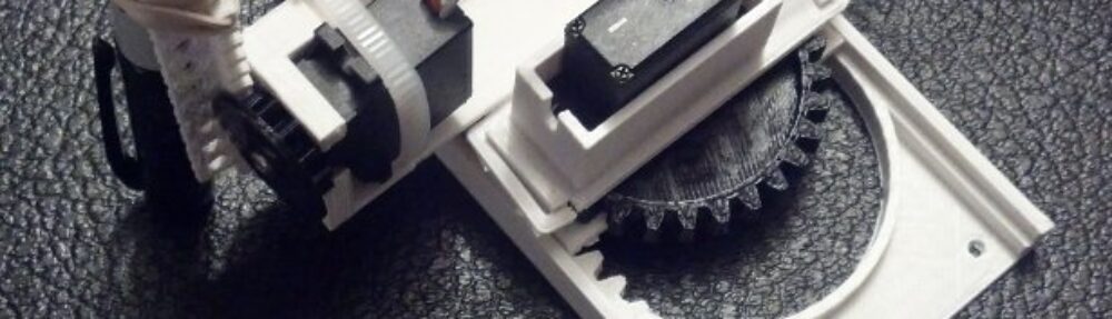
This Tiny 3-axis CNC software guide is designed to assist the user of the robot in quickly and easily operating their robot. The TinyCNC robot uses three separate pieces of software to operate as a 3-axis CNC or, if you prefer, a drawing robot. These are an Arduino sketch, a Processing sketch, and a plugin for Inkscape. ((For the sake of brevity and to maintain a focus on the operation of this particular robot, this guide assumes the user is able to install these programs, install any necessary drivers, and troubleshoot any problems with their particular computer, operating system, and microcontroller.)) Each piece of software in this toolchain is entirely open source and multi-platform.
- An Arduino sketch is necessary for the Arduino attached to the robot to interpret basic Gcode CNC instructions. The only instructions this sketch will interpret are G1 (to move the robot to a particular XY coordinate) and M300 (to raise or lower the Z axis). The sketch “listens” for a line of Gcode, interprets it, and then moves the robot accordingly.
- A Processing sketch is used to open a text file containing Gcode and send the commands over a serial USB connection to the robot.
- The open source vector graphics program Inkscape is used to convert vector graphic images into a series of Gcode instructions, using an extension.
There are three different Arduino sketches that provide an increasingly sophisticated level of sophisticated operation. This guide will assist the user in using each of these three sketches, culminating in the ability to draw images.
- Download all software
- Download and install Inkscape.
- Download and install the Arduino IDE.
- Download and install Processing.
- Download the Inkscape extension for outputting G-Code for the MakerBot Unicorn Pen Plotter by Marty McGuire. (Look for the download button along the right side of the page)
- Download the various TinyCNC sketches. (Look for the download button along the right side of the page)
- Setting up Arduino IDE
- Install the TinyCNC sketches
- Copy the “TinyCNC_Shapes.ino” Arduino sketch folder into your Arduino IDE’s sketch folder.
- Copy the “TinyCNC_WASD.ino” Arduino sketch folder into your Arduino IDE’s sketch folder.
- Copy the “TinyCNC_Gcode.ino” Arduino sketch folder into your Arduino IDE’s sketch folder.
- Using a USB cable, connect your Arduino microcontroller to your computer.
- Open the Ardiuno IDE.
- Select your particular Arduino variant board by going to “Tools -> Board” and choosing it from the list.
- Select the serial port for your Arduino by going to “Tools -> Serial Port” and choosing it from the list.
- The following slideshow will take you through the above steps.
- Install the TinyCNC sketches
- Draw Basic Shapes
- Open the Arduino IDE.
- Open the “TinyCNC_Shapes.ino” by going to “File -> Sketchbook -> TinyCNC -> TinyCNC_Shapes”.
- Upload the “TinyCNC_Shapes.ino” sketch into your Arduino by going to “File -> Upload” or clicking the arrow upload button.
- If you have a pen attached to the Z axis, the robot should start drawing a rectangular spiral.
- The following slideshow will take you through the above steps.
- Control the Tiny CNC with the Keyboard
- Open the Arduino IDE.
- Open the “TinyCNC_WASD.ino” by going to “File -> Sketchbook -> TinyCNC -> TinyCNC_WASD”.
- Upload the “TinyCNC_WASD.ino” sketch into your Arduino by going to “File -> Upload” or clicking the arrow upload button.
- Open the Arduino Serial Monitor (which lets you communicate with the Arduino) by going to “Tools -> Serial Monitor”. (You can also click “Control + Shift + M”)
- The Arduino Serial Monitor will appear as a popup window with a box for entering text, a “Send” button, and a large field where it will display any messages coming from the Arduino.
- Use the “WASD” and “OL” keyboard keys to control the robot by typing a character into the Serial Monitor and clicking “Send” or hitting the “Enter” button.
- The robot will move left or in the -X direction (“A”), right or in the +X direction (“D”), forward or in the +Y direction (“W”), back or in the -Y direction (“S”), raise or in the +Z direction (“O”), and lower or in the -Z direction (“L”).
- The following slideshow will take you through the above steps.
- Setting up Inkscape
- We’ll need to install the Inkscape extension for outputting Gcode in order to convert SVG files into Gcode.
- Copy the extension files into your “Inkscape/extensions” folder. If you choose to use PortableApps.com version of Inkscape, you’ll find the extensions folder at “InkscapePortable\App\Inkscape\share\extensions”.
- Create Gcode with Inkscape
- Open Inkscape.
- Go to “File -> Open” and locate the SVG (vector graphics) file of your choice.
- Why not try this Open Source Hardware logo (3135 downloads ) ?
- There are some nuances to converting SVG files into Gcode, which I will cover at the end of this post.
- Go to “File -> Save As” and type in the file name of your choice with the file extension “.gcode”.
- Under “Save as type:” choose “MakerBot Unicorn G-code (*.gcode)” and click “Save”.
- A popup window will appear with several settings. Make sure the “Pen Up Angle” is set to exactly “50.0” and the “Pen Down Angle” is set to exactly “30.0”.
- The following slideshow will take you through the above steps.
- Control the Tiny CNC with Gcode (and draw a picture!)
- Open the Arduino IDE.
- Open the “TinyCNC_Gcode.ino” by going to “File -> Sketchbook -> TinyCNC -> TinyCNC_Gcode”.
- Upload the “TinyCNC_Gcode.ino” sketch into your Arduino by going to “File -> Upload” or clicking the arrow upload button.
- At this point you can close the Arduino IDE – or leave it open if you wish. However, make sure the Serial Monitor is closed since the Arduino Serial Monitor will interfere with the Processing program’s ability to communicate over the serial connection.
- Open Processing.
- Open the “SendingSerial003.pde” Processing sketch by going to “File -> Sketchbook -> Sketches -> SendingSerial003”.
- Change the “filename” variable from “r2d2a” to whatever your Gcode filename happens to be. (The program will assume a “.gcode” after the file prefix.
- Run the Processing sketch by going to “Sketch -> Run”, clicking “Control + R”, or clicking the triangular “Run” button.
- The Processing sketch will open a tiny popup window and start to stream Gcode commands to your robot and the robot should perform each command in turn. The commands will be echoed in the black message area at the bottom of the Processing screen.
- The following slideshow will take you through the above steps.
- Subsequent Gcode Operations
- Once the user has uploaded the “TinyCNC_Gcode.ino” sketch to the Arduino, the user does not need to bother with the Arduino IDE again.
- From this point forward, the operation of the robot becomes remarkably simplified. The user may simply craft Gcode with Inkscape and then send that Gcode to the Arduino operating the robot using the Processing sketch. If the user wishes to simply draw images from a library of Gcode files,
- Converting SVG files to Gcode, Special Considerations
- Layers and Objects. Text, complex paths, paths that have been grouped together, and objects are not as easily converted directly into Gcode using the Inkscape plugin instructions above. In order to simplify the SVG file for converting into Gcode, it is necessary to break up the various groups and objects into one set of paths the extension can translate. The easiest way to do this is to:
- Select all the contents of the image by using the command “Control + A” or going to “Edit -> Select All”.
- Ungroup all the groups (often these aren’t obvious) by using the command “Shift + Control + G” or going to “Object -> Ungroup”.
- Convert all the objects to paths (the Gcode converter only converts paths into Gcode) by using the command “Shift + Control + C” or going to “Path -> Object to Path”.
- Break all the paths apart by using the command “Shift + Control + K” or going to “Path -> Break Apart”.
- Subtract the various paths from one another by using the command “Control + -” or going to “Edit -> Difference”. (Note: This may make your image look really weird. Don’t panic. This is entirely normal and actually a good sign.)
- Once steps 1-5 have been completed, try to save the SVG file into Gcode. If you get an error, repeat steps 1-6 and try to save the file into Gcode again. Sometimes I’ve need to go through steps 1-6 as many as two or three times.
- The following slideshow will take you through the above steps.
- Size. The image you’re using may be much larger than the robot you’re using can accommodate. If you are using the TinyCNC robot platform, you will want to make sure your image is only about 3″ wide by 2″ tall. Much larger than this and your robot may have a difficult time drawing the image. The best way to ensure your Gcode will only describe an area your robot can draw is by resizing the entire page to be only 3″x2″.
- The easiest way to do this is to:
- To change the “page” size of the document, go to “File -> Document Properties” or click “Shift + Control + D”.
- A new popup window will appear with the current page dimensions listed under “Custom size”.
- First change the “Units” to “in”, then adjust the “Width” to “3.00” and the “Height” to “2.00”.
- Click the “X” button in the top right corner of the popup window to exit the Document Properties.
- You should now see your SVG image on a different sized page. You may need to zoom in or out using the “Z:” box in the bottom right corner of the window.
- The following slideshow will take you through the above steps.
- Layers and Objects. Text, complex paths, paths that have been grouped together, and objects are not as easily converted directly into Gcode using the Inkscape plugin instructions above. In order to simplify the SVG file for converting into Gcode, it is necessary to break up the various groups and objects into one set of paths the extension can translate. The easiest way to do this is to:
Back to the Drawing Robot AFRON Ultra Affordable Educational Robot 2013 Design Challenge Entry.
Default Series Title