Maker Faire 2016 Drawing Robot Presentation Slides

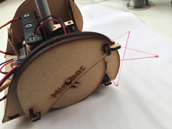
Maker Faire Bay Area 2016 was a wild ride!  If you were able to come to my presentation on tiny drawing robots – thank you!  If you weren’t able to make it, I’m sorry I missed you.  I got to see some old friends1 and make some new ones2 , which is probably the biggest reason I blog and exhibit and present at Maker Faire.

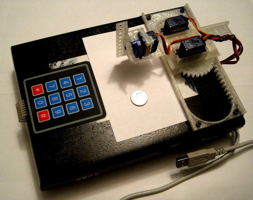
Admittedly, I was a concerned that I would be talking to a bunch of empty benches, that I would run through all of my slides in the first five of my allotted 25 minutes, or that I would be presenting to a completely silent crowd.  If you came to the presentation, you got to see that none of those things happened.  I started talking to the crowd a little early, answering some questions and letting people try out my demonstration robot with the keypad.  When I actually started the presentation the benches were full and there were several people standing around them.  There were some really great questions from the audience and lots of enthusiastic ideas.

If you didn’t come to the presentation, you missed both of my daughters making impromptu appearances, one uncooperative robot, one cooperative robot, and you had the chance to grab a “maker card” and actually use my demonstration robot.

As promised, I’ve posted my slides (above) so you can relive the magic.

  1. Like you Kongorilla! []
  2. Like you Robert, Vanna, Elijah, and Matt []

Care and Feeding of Your TinyCNC Drawing Robot

Draw on the go with a small Arduino-powered CNC robot!

I’m bringing this fully assembled robot to Maker Faire on Sunday!

During my presentation at Maker Faire on Sunday I’ll be showing people how to build their very own TinyCNC drawing robot.  However, some things are best done in a written form – so you can refer back to the instructions while you work.

  1. Print these parts on a well-calibrated 3D printer
  2. Use the 8 plastic printed parts, 3 servo motors, and one zip tie to assemble the robot
  3. Wire the robot to your favorite microcontroller
  4. Program your microcontroller to make your robot do nifty things

How to Build a Tiny Drawing Robot at Maker Faire Bay Area 2016

Drawing Robots at Maker Faire 2016!

Drawing Robots at Maker Faire 2016!

I’ll be doing a short presentation on how to build (and operate) a tiny drawing robot at Maker Faire Bay Area 2016.  My time slot is Sunday May 22, 2016 from 11:00am to 11:25am at the Make: Electronics stage in Zone 2 aka “Expo Hall.”  You can see where I’ve outlined Zone 2 and the Make: Electronics stage in the above picture.

If you’re around, I’d love to see you.  However, I know how hectic Maker Faire can be and how difficult it can be to get anywhere.  If you want to hang out, I’m planning to go to the Maker Paella Dinner on Friday night on the Maker Faire grounds and the Hackaday meetup on Saturday night O’Neill’s Irish Pub in San Mateo.1

  1. Tickets to the Hackaday meetup are free – just follow the link and RSVP []

Vertical Pen Test by Jens Clarholm

Vertical Pen Test by Jens Clarholm

Vertical Pen Test by Jens Clarholm

Jens Clarholm has been hard at work to find the best pen for his Circlon1 drawing machine.  The Circlon holds pens vertically as it draws, which necessitates pens that draw quickly and smoothly.  

You should definitely check out Jens’ detailed and thoughtful review.  For the sake of posterity, the winners were Pentel Energel Deluxe RTX and the Pilot G-2 07.

If you need to find the best horizontal pen for a drawing robot, you may find my review from last year helpful.

  1. Spirograph-style []

Mirobot by Ben Pirt

Mirobot, ready for drawing!

Mirobot, ready for drawing!

A few weeks ago I stumbled across the Mirobot website after seeing a post on the Arduino forums.  The creator, Ben Pirt, designed this cool open source drawing robot that is driven over WiFi to roll around and draw.  One of the nifty things about this project is that the robot is that it has an almost unlimited drawing size.1

Ben was kind enough to answer a few questions about his project:

  • What is the Mirobot?
    • Mirobot is a simple drawing robot that’s designed to help children learn about programming and technology. It’s all open hardware and software so once you’ve done some of the basic exercises and you’ve built up your confidence you can start hacking it to do different things. It’s battery powered and WiFi-enabled which means you can put it on your home network and just start using it from any web enabled device.
  • How did you get started in robotics?
    • This is my first robot really! Although I guess back in the 80’s was when I first got my hands on a robot when I used the BBC Turtle. I was lucky because my Dad was a teacher and was involved int he early days of computers in schools – I was his willing guinea pig. Every school holiday he would bring something home to play around with and the Turtle was always one of the most popular things.
  • Why did you decide to work on a drawing robot? Where there any other robots that inspired you?
    • A couple of years ago I took my kids to the Science Museum in London (worth a visit if you ever get a chance) and saw one of the original Turtles that I’d used in my childhood. After being immersed in technology for a while now it struck me that what was then a very expensive and complex machine could now be constructed relatively easily and at low cost. In the era of the original Turtles you were lucky if you had one per school, but with an open hardware approach and using open platforms like the Arduino, much of the development is already done. I’m now able to build a robot that improves on the original (it has batteries, uses WiFi) at a fraction of the cost.
    • But the real reason I decided to start work on the project was so that I could build it with my kids. We built the first release over Christmas and it’s evolved from the learning that gave me.
  • Who do you see using these robots? What do you hope they’ll learn as they build and program the robot?
    • It’s designed with children in mind – it’s been made easy to assemble and I’ve put a lot of time into making sure the PCB is easy to solder. I’m hoping to work with schools so that a class can all build their own robots and then start learning by using them. When you build the robot yourself you have a much greater appreciation of where it came from. As you put together the PCB I take the opportunity to explain what each piece is doing so even if you don’t fully understand how it works, you still get more of an understanding about what it’s doing. You also get more of a mechanical understanding about how things fit together because nothing is hidden and you can see what everything is doing. Once you start using it you can obviously develop your understanding of some basic programming, but once you’ve mastered this there are lots of other ways you can learn by modifying it;
      • – you can customise the web application and learn Javascript / HTML
      • – you can program it from Javascript, either in-browser or via Node.js
      • – you can modify the firmware and add functionality to the robot
      • – you can add sensors to develop what it’s capable of
  • How big a drawing is the robot capable of? How complex a drawing?
    • Well the robot is battery powered and wireless so the question is how big is your piece of paper? I do have some plans to make a massive drawing at some time!
  • Besides drawing what else could people do with this robot? Do you think there are any commercial or industrial applications?
    • I definitely see Mirobot as a base for future experimentation so I can see people adding sensors and making it autonomous. Maybe someone will use it as a base to make the cleaning robots like in the Fifth Element! I’ve intentionally brought out any unused pins on the Arduino to a header so that it’s easy to add hardware.
  • Why did you choose to go with a custom designed board rather than an Arduino with a motor shield? What other applications do you see for the Mirobot board?
    • I originally started with a shield for a regular Arduino but found that it turned out to be quite expensive (and one of the goals of the project is to make it as low cost as possible) and also quite bulky. It began to impact on the physical design of the chassis and was quite difficult to mount (it required screws, and these cost money and add to the complexity of the construction process). I also wanted people to be able to completely build their own robot so liked the idea that you really do build everything. By building a custom board I can make it fit perfectly into the design of the robot.
  • Why did you choose open source?
    • I’m a big believer in the Open Source approach and I think this is the perfect project for it. If the aim of this project is to get it into as many children’s hands as possible then allowing anyone to make it, and also to learn from the making process, is a key part of that.
  • What’s your favorite thing to draw with the Mirobot?
    • At the moment my favourite test pattern is the classic 5 pointed star which can be nicely drawn in LOGO by doing:
      • repeat 5 [
      • forward 100
      • right 144
      • ]
    • Although I’m still learning! I’d like to teach it to do some portraits by converting vector images to drawing commands.

Thank you to Ben for taking the time to share more about his project!

Mirobot - drawing!

Mirobot – drawing!

  1. As long as the paper, pen, and batteries hold out! []

Doodle Clock by Ekaggrat Singh Kalsi

Doodle Clock picture totally swiped from Hack A Day

Doodle Clock picture totally swiped from Hack A Day

I found the Doodle Clock featured by Hack A Day in March of 2012 as a result of a comment on that side.  It’s not a traditional drawing robot as I feature on this site, but it does have the most important parts – a robot that creates some kind of drawing using a typical drawing instrument.

The setup appears relatively simple – some metal arms, motors, and what I would guess is an Arduino microcontroller of some kind.  Although the video doesn’t seem to show the eraser implement, the robot has an almost hilarious method of wiping the drawing surface using the side of the pen holder.1 There isn’t a ton of information out there about this robot – basically just the write up on Hack A Day, the YouTube video, and then a few comments in both forums.2 Fortunately, in the video comment section the creator does provide a brief explanation of the math underpinning this nifty robot:

Use inverse kinematics to find the angles of the motors like the following equations: 
float l1 = 80.4; // the length of the shoulder 
float l2 = 88; // the length of the elbow
double cb2 = 2*l1*l2;
double c2 = (sq(x) + sq(y) - sq(l1) - sq(l2)) / cb2; 
double s2 = sqrt(1-sq(c2)); 
double k1 = (l1 + l2 * c2); 
double k2 = (l2 * s2); 
double base_ang = rtod((atan2(y,x) - atan2(k2,k1))); 
double elbow_ang = rtod(atan2(s2,c2)) + 90;
myservo1.write(base_ang); myservo2.write(elbow_ang);

Many robotic arms use inverse kinematics math to calculate and control position and movement.  Although not as complex, the Doodle Clock and Linus use this same math.  Now, if you’ve read this far – why not check out this pretty amusing video of the Doodle Clock in action?

  1. I would guess there’s a small cloth or some thing glued to the side []
  2. Although, I just saw a post on Engadget about it too []

Piccolo by Diatom Studios

Piccolo - version 4

Piccolo – version 4

The Piccolo by Diatom Studios is a tiny CNC robot – a huge source of inspiration for me.  I first heard of the Piccolo in about February of 2012 when they got a lot of blog and press coverage after they launched an excellent introduction video and website.  The award winning design1 features lasercut acrylic parts, three micro servos, and a pen holder.  However, since the robot is a 3 axis CNC rather than just a 2 axis CNC with a pen lift, the possibilities for extending, tinkering, and hacking the platform are basically endless.

Although their Piccolo website has been relatively quiet lately,2 there have been several interesting developments.  The Diatom Studio crew has posted lots of files, instructions, and code up in their GitHub account, they’ve got a ton of pictures in their Flickr pool that appear to show the design evolution of the Piccolo, and there’s even a LittleBits powered version of their platform.

The latest version shown in their Flickr pool provides a lot of insight into their design process, part choices, and a hit of things to come.  The latest Piccolo pictures features an Arduino Pro Micro powered circuit board and three servo connectors upon which the lasercut parts are layered to build up the robot.  Unlike prior versions of the robot which appeared to require several different thicknesses of lasercut material, this version seems to require only one thickness of wood, one thickness of acrylic, and one thickness of what appears to be paper.  If I were to guess, I would suppose the lasercut paper is used for spacers between the layers to provide clearance for parts to slide through.

This slideshow requires JavaScript.

Lastly, if you haven’t checked out the video, you really need to do that now.  I’m pretty confident that you’ll fall in love with this little robot too.

  1. Scroll to the bottom to see the award links []
  2. Still no launch date – sad face []

PlotClock by Joo

Thingiverse citizen Joo has just shared the hands down, cutest robotic drawing dry erase clock you’ve ever seen ever, called the “PlotClock.”  This is the kind of awesome robot that makes me want to drop everything I’m doing to build one.  Much like the Piccolo video, I could watch this little clock write/erase the time all day.  The design is inspired and elegant, using one servo to rock the other two backwards for a pen lift, and using a small “cup” with an fuzzy bottom to transform the pen into an eraser.

Joo has kindly shared lots of photos and instructions on this FabLab wiki and the code on Github.

So…. Does anyone in the SF Bay Area have a laser cutter they could let me use?  🙂

Hat tip and monocle nod to Tbuser for pointing project out to me.

Linus the Artistic Robot by PixelatedThoughts

Linus the Artistic Robot

Linus the Artistic Robot

I’ve always intended that this website be about more than just the few robots that I’ve built.  It’s also about other robots that perform art, especially those that draw.  I’m hoping to make these kinds of “plotter profiles” a more regular thing on this blog.

Every once in a while I do a search on Kickstarter just for drawing robots.  Last week I happened upon Linus – a simple drawing robot which uses open source software.  With only a few days to go on the campaign, I reached out to the creator Jacob Balthazor of PixelatedThoughts.com and asked him a few questions.

  • Why a drawing robot? Were you inspired by any other project in developing your robot?
  • I guess I was attracted to the poetic irony of a robot; a word we attribute with being mechanical, orderly and blind to creativity, that can create a piece of art in the very human way of dragging a pen across paper. I am working on some software to take this idea further. The program would make Linus randomly grab a picture off of the internet and interpretively draw it daily. This way you would always have a new piece of art every day, freeing Linus from the creative bounds of the users creativity.
  • Have you used it for anything else other than drawing? What else could you do with this robot?
  • Because of Linus’s simplicity it can be very easy to modify and and even swapping the utensils he hold can lead to vastly different functions. I am very excited about the possibility of using the circuit scribe pens (a pen that can essentially draw a wire) with Linus to draw intricate circuit patterns on paper. I am interested to see what other applications people come up with for Linus.
  • What was the hardest part about designing this robot? Why did you choose to go with a inverse kinematics instead of an XY gantry?
  • The most difficult part of creating Linus was solving the inverse kinematics (difficult non linear geometry problem) math problems to translate the x and y locations that the drawing programs uses to the angles that the robots arm would take to go to those locations on the paper. Tthe mathematical solutions are something that even take a computer a bit of time to compute which is difficult when the robot needs the equations computed fifty times per second. Most other robots are not constructed with arms for this very reason and have mechanisms that move them directly in x and y directions without the need of an equation doing space transformation between. But it was the use of an arm in Linus which allowed us to keep the cost of parts down. Linus would have been less reliable and significantly more expensive if we constructed it with an XY gantry.
  • Why servos instead of steppers?
  • Servos offered a more complete and compact solution. If steppers were used instead, a couple things would have happened with the design. First Linus would have grown in weight and size messing with the small form factor. The weight of the steeper on the suspend second joint could potential cause problems. Because steeper motors without gearing don’t have quite the resolution as servos, a gear system would be needed adding quite a bit of complexity, increasing the price and number of things to fail. The servos allowed for great resolution, and ultimately kept the design elegant and less expensive to produce.
  • What is the drawing area?
  • The drawing area of Linus is currently 4.5 inches square. But we are working on a way to expand the drawing area potentially to six by six through messing with the inverse kinematics equations and software.

Thanks Jacob!  Good luck with your Kickstarter campaign!

TinyCNC Two steps forward, one step back!

Intermediate version with minor design changes

Intermediate version with minor design changes

Above is a picture of the most recent version of this robot.  It includes two nifty changes and one design aspect1 that will probably involve me using design elements I had discarded earlier.  Here’s what I’m working on:

  1. No tools.
    1. The problem with using set screws to affix printed gears to the servos is that too little tightening means the gears will slip2 and too much tightening will strip the micro servo gears almost without warning.3 I’ve redesigned the pinions (gears) so that you can just push the servo horn through the gear and then push it onto the servo gear.  If you wish, for smoother and more reliable operation, you can always add the servo set screw to the servo horn, but it isn’t necessary. Best of all, you’re not going to strip your micro servo gears when you do this.
    2. This design did not come without concession.  I had to compromise on my ideal of removing overhangs.  All published parts to date have been printable with completely flat bases and without even slight overhangs to improve and ease printability.  In order to create the smaller pinion above, I had to add an overhang.  However, it’s a short overhang, which should still easy enough for most printers.
  2. Redesigned motor mounts.  I’ve changed the motor mounts so the fit the4 micro servo motors I purchased.  Hopefully they’ll fit yours too.  🙂  
  3. Improving the X axis.
    1. I’m reasonably happy with the X axis.  It’s not idea – but it works.  I’m designing a way to invert the X rack, so it is trapped by the X pinion and the entire robot can stay together.  This is still in an early design stage and so far requires lots of other design changes, so I’m trying to solve the Z axis and Y axis problems before working my way out to a better X axis.
  4. Improving the Y axis.  
    1. The problem.  The Y axis I created for the version 0.29 steady as the the Y axis in the version 0.18.  With the earlier version the Y axis slid on either side of the X motor mount, so that it was difficult for it to wobble side-to-side.  The newer version only slides along one side and incorporates this a long “fin” intended to stabilize the Y axis’ side-to-side motion.  That “fin” also had a long groove in it that was designed to help with up-and-down motion stability.  I think it worked for the most part.  In reality, the Y axis can wobble as much as a 1-2mm to the left and right in the new version.  One of the reasons I moved to the system used in the version 0.29 is that it allowed me to place all the motors in a very compact area while keeping the Y axis relatively short.  This conserved plastic, kept the part sizes small, and kept most of the mass in the robot in one area – which I felt would help reduce wobble.  
    2. The solution?  
      1. One obvious route is to go back to the Y axis alignment system used in version 0.18, where it slid along both sides of the X motor mount.  I moved away from this system because there didn’t seem to be a good way to mount the Z motor.  Not having a really great solution to mounting the Z axis motor isn’t that big a deal.  The current motor configuration is reasonably symmetrical and aesthetically pleasing, but not critical by any means.  As long as the robot isn’t operated at ridiculous speeds, the unsymmetrical motor mounting shouldn’t be that big of a problem.  While I have another design option, I think this is the system I’ll end up using.
      2. The other option is to cut a long groove in the Y axis with a tab sticking out of the X motor mount5 to keep it steady. As the Y axis slides back and forth, it should be kept in line by the tab.  Similar to this, I could also put a groove in the X axis where the Y axis slides to keep the Y axis in line.
  5. Improving the Z axis.
    1. The Z axis is a little wobbly.  While a little wibbly-wobbly-ness is to be expected, when there’s a little introduced with each axis, the effect is compounded in the end result.  This isn’t a problem for large gross manipulations, but becomes more obvious when drawing.  One of the reasons I’m tuning this robot to draw well6 is that if it can draw well, chances are it can do other tasks well too.
  6. Improving the X axis.
    1. I know this isn’t in any obvious order.  🙂  However, I’m reasonably happy with the X axis.  It’s not idea – but it works.  I’m designing a way to invert the X rack, so it is trapped by the X pinion and the entire robot can stay together.  This is still in an early design stage and so far requires lots of other design changes, so
  7. Things to try out.
    1. Drawing without pens.  Recently the idea occurred to me that drawing with a pen may not be ideal.  A pen is designed for the human hand – so it has heft, grip, length, and all sorts of other attributes that aren’t ideal for a robot.  However, the pen cartridge/ink reservoir is shorter and has considerably less mass.  So, why not just pull that out of a pen and scrap everything else?  Heck, there might even be an interesting way to incorporate the pen’s own spring into the design.  I think it would be incredibly interesting to use that spring as the basis for a pen holder.7
    2. Smaller, more numerous teeth.  I honestly don’t know if these are beneficial.  I’m guessing there’s a law of diminishing returns when it comes to using smaller teeth.  Smaller teeth are harder to print and may be easier to break or more prone to skipping.  On the other hand, it is possible they might allow for smoother and more reliable operation.  I’ll try it both ways and let you know!
    3. Closer meshing between pinions and racks.  I’ve designed the robot with a degree of “slop” between the pinion and rack teeth.  This is so that I can make parts that I know will fit and work on many different robots.  I like to think I’ve got my Replicator 1 dialed in pretty well – so it’s entirely possible I could place the teeth closer together.  I figure closer meshing probably involves more stress on the motors, but that’s another problem for another day and another blog post.  😉
    4. Designing with fasteners in mind.  One interesting solution from Joseph is to put zip ties around the various parts to keep them in place.  The zip ties are apparently smooth enough that the parts still slide and stay together.  I love this solution.  I think it could be even better if zip tie solutions were further incorporated into the design as fasteners.
    5. Putting it all together.  The new-ish design you see at the top allows for the use of servo set screws without actually requiring them.  They’ll help, but aren’t critical.
  1. The Y axis []
  2. Even with foam rubber stickers! []
  3. There’s a slightly sickening crunch as you do.  I don’t recommend it []
  4. Many, many []
  5. This makes more sense if you’re inside my head []
  6. As well as can be expected for a bunch of plastic parts and cheap motors []
  7. I’m not sure if this would be cannibalistic or meta.  Thoughts? []