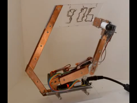
Ytai showing off his plotter art at Codame 2013
Easily one of the most memorable aspects of exhibiting at this year’s Maker Faire Bay Area was getting to meet and interact with lots of other Makers. Ytai Ben-Tsvi had built and brought a pen plotter of his own design – and it was amazing.
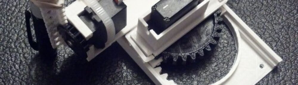
Ytai’s pen plotter used an Android tablet, his IOIO OTG board ((Ytai’s succinct description of the IOIO board says it all, “The IOIO-OTG is a printed circuit board for electronics hobbyists and prototypers, which addresses a very common problem: how do I use my {computer, tablet, phone} to control my {robot, dish-washer, cat-feeder, etc.}.” )) , two stepper motors, two comically large spools, and lots of custom code to turn pictures taken with the tablet into instant portraits on the fly.
His plotter was everything a Maker Faire exhibit should be – highlighting the intersection of art and technology while inviting the audience to be a part of the action. Can you believe this guy was reluctant to call himself an artist?
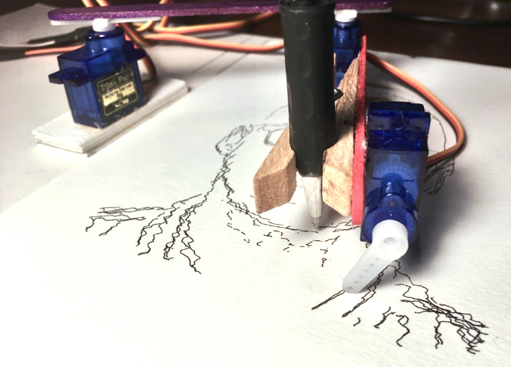
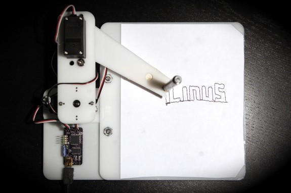
After Ytai was invited to participate in the Codame 2013 art-tech festival ((An art-tech festival?! Why the hell aren’t there more of these things?!)) he decided to create an entirely new drawing algorithm to turn images into a single line drawing which appears to be sharp scribbles up close and a detailed image from a few meters away.

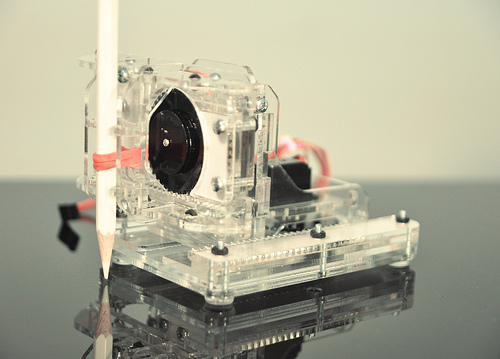
Photo transformations with Ytai’s ScribblerDemo
What I love about Ytai’s drawing process is that it produces a drawing with a sense of whimsy and movement without the hard number crunching necessitated by a Traveling Salesman Problem ((Link to blog post showing a method)) style drawing. ((Doesn’t exactly hurt to have a cute kid as a subject either)) By allowing the algorithm to have lines cross over one another, something the TSP method eschews with its own aesthetic, Ytai’s drawings essentially gets “for free” extra dark patches where lines closely intersect. ((Having played with TSP drawings a lot, I have discovered that finding the right balance between lightness versus darkness and simplicity versus complexity and quick versus glacial to be… maddening. Like H.P. Lovecraft maddening))
Looking at this drawing, it seems to me that an SVG created from his algorithm conveys so much more meaning with far less points than a TSP file. At least for my own PlotterBot, far fewer points would also mean a much faster, and more satisfying to watch, drawing. I would estimate that in the time it took Ytai to cover a wall, I might have been able to create one, perhaps one and a half, drawings. And, as any good Maker does, Ytai has shared the fruits of his hard work in the form of the source code on Github.
Default Series Title