OpenSCAD Rendering of Mini CNC
My daughter and I recently signed up to take part in Make’s Robot Hacks’ project. Make was kind enough to send me a box of parts, including the Make Ultimate Microcontroller Pack and a bunch of servos.
The catch? We had to actually create something and share my progress by November 20. From the time my parts arrived, this was exactly 14 days. 🙂
I had a number of ideas about what I wanted to make – an automated Robo Hand, electronically released spring loaded wings, a little servo-powered walking robot, and a dozen of other smaller ideas. My daughter’s ideas were significantly more ambitious – flying, wall crawling, dancing, hearing, seeing, talking, thinking robots. The idea that I kept coming back to was a tiny little CNC robot using servos powered by an Arduino – something I had first seen in February of 2012 with Piccolo – the tiny CNC-bot by the Diatom Studio team.
My adventures building robots aside, I still consider myself a “newb.” However, I knew the basics of what I needed to accomplish:
- Drive three servos with a single Arduino
- Make each servo drive an axis of movement
- Figure out a way to translate 180 degrees into linear movement
So, for what it’s worth, here’s my process:
Driving Multiple Servos with a Single Arduino
Since I had never (!) driven a servo with an Arduino, I needed to figure out how to manipulate at three servos at the same time. Fortunately, the Arduino “Sweep” example explicitly states that it’s capable of controlling eight servos.
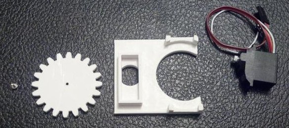
Connecting them was significantly simpler than I was anticipating. For the Batan B2122 servos I had, the brown wire was ground, orange wire was positive, and yellow wire was the “control” that would have to be connected to one of the Arduino’s digital out pins. The easiest way for me to wire up the three servos was through a small breadboard.
Once the servos were wired up, it was a matter of loading up the Sweep example and driving a single servo back and forth. By adding a few lines, I was able to drive two servos, and then three.
Using a Micro Servo Motor to Drive an Axis of Movement
The Batan B2122 micro servos are not continuous rotation motors – they only have a 180 degree range of movement. Most CNC machines use stepper motors which are strong, fast, precise, and can rotate continuously forwards or backwards. Servo motors, by contrast, are smaller, cheaper, slower, and unless they are specifically designated as “continuous rotation” have a limited range of movement.
I considered two different ways, each with their own merits, of using a limited range of motion motor to drive an axis of movement. The first way I considered was using a spool and twine to drive each axis – similar to the Printrbot Simple and WaterColorBot. This is an excellent and cheap alternative to using expensive precision toothed belts to control movement. The reason I didn’t use this method is that it would have required a spool for the twine, and some form of rails or metal rods, and of course twine. My concern is that this would have been a bulky solution for such a small robot.
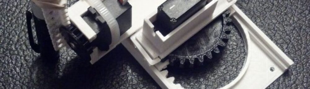
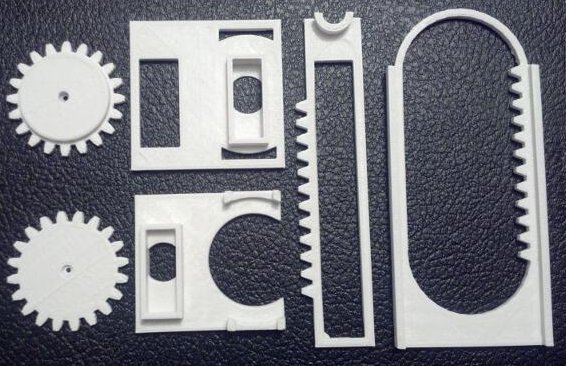
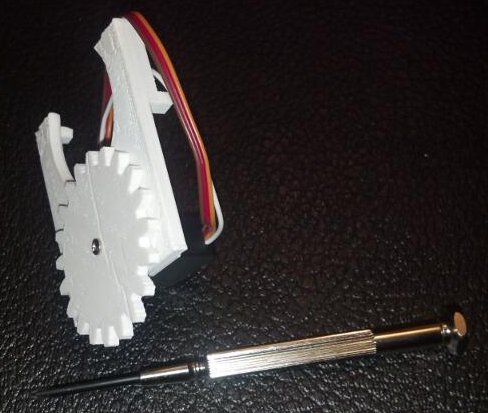
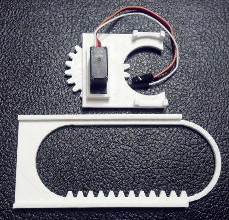
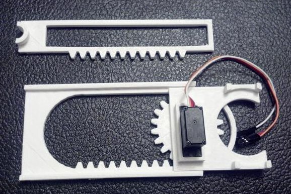
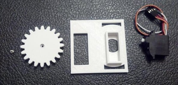
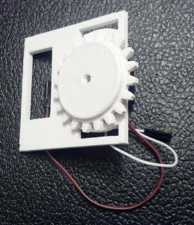
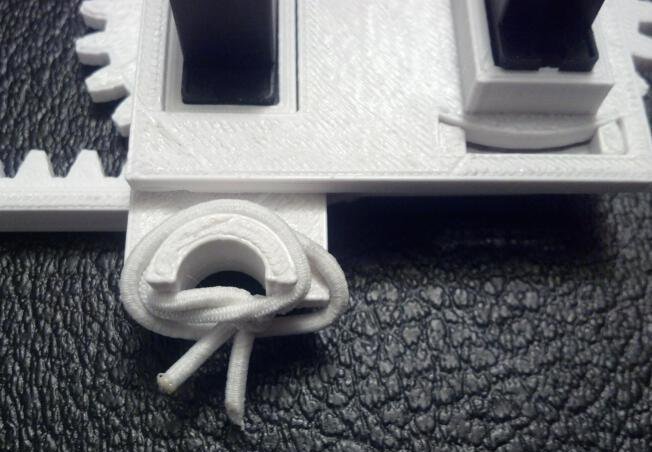
The second method, the one I decided upon, was to use a rack and pinion to turn the rotational motion of the servos into linear motion. One benefit of using a rack and pinion is that the rack itself removes the need for rails or precision rods, spools, and twine – all while providing a sturdy framework for adding additional axes.
Translating 180 Degrees into Linear Movement
As I alluded to above, the micro servos only have 180 degrees of movement. Thus, a gear (or pinion) attached to a servo would only be able to drive the rack by 1/2 of its circumference (or 180 degrees). Keeping that in mind, I chose a gear size that would produce the desired freedom of movement. I settled on a gear radius of about 20mm because it created about 2.5 inches or 62.8mm [ (2 * π * 20)/2 = 62.8 mm] of movement.
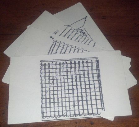
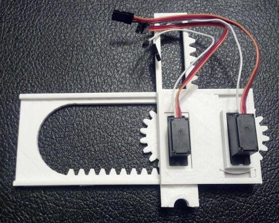
Moving a pen over a 2.5″ square would enable me to create nifty little robo-drawn post-its, bespoke business cards, or an auto-signature device.
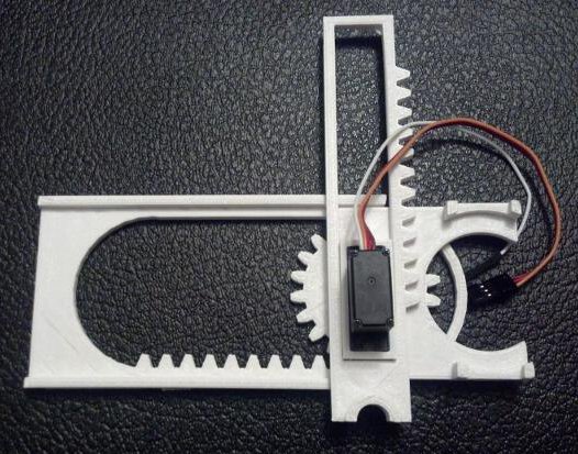
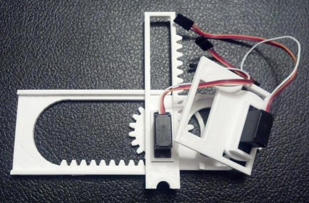
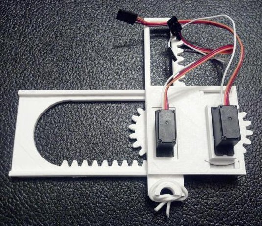
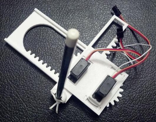
Here’s what I have so far:
Next Steps…
Since the robot isn’t actually capable of doing a whole lot yet, I’ve got a bit to do still:
- I need software to interpret XY coordinates or GCode into rotational degrees
- Get write a Processing or Python script to send the XY coordinate or GCode to the Arduino
- Slightly redesign the two gears (well, pinions) so that it’s easier to attach them to the servos
- Create a new Y rack that can hold the third servo (for the Z axis) and a pen for drawing
Since I’m only intending to use this little CNC for small drawings, I don’t really need a huge Z axis lift – even a few millimeters should be sufficient. I was considering cheating a little and just making the “Z axis servo” just lift the front of the robot off the surface.
Even though I’ve got a bit of work ahead of me, I’m pretty happy to have a working proof of concept of a robot of my very own design!
If you would like a little robot like this of your very own, you can find my 3D printable files on Thingiverse and the Arduino code is pretty much the stock “Sweep” example. Stay tuned because I’m looking forward to turning this into a legit itty-bitty CNC drawing robot.