Tiny 3-Axis CNC Drawing Robot – Software Update and Design version 0.29 postmortem

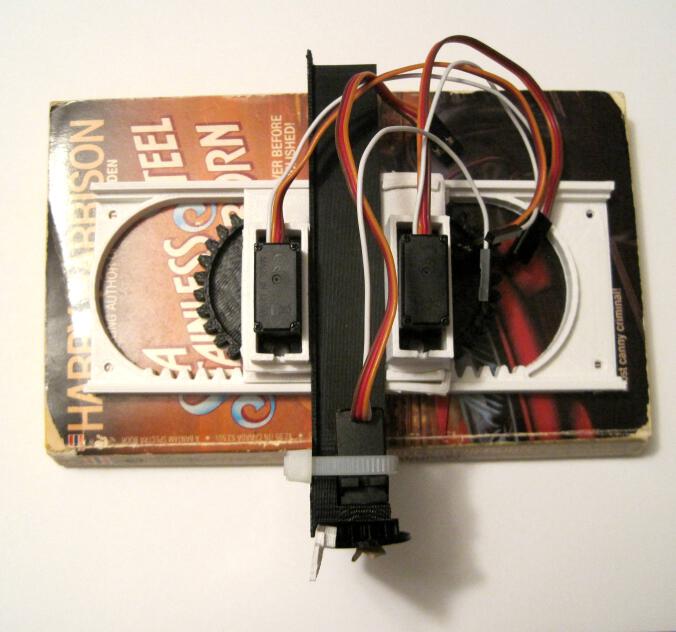
Above is a very short video showing the Tiny 3-Axis CNC, powered by an Adafruit Trinket, using all three axes.

In order to push the Tiny CNC robot design further, I had to actually wire it up and test it.  Only by actually trying to put it through its paces am I able to detect design defects for correction/improvement in the next version.  What follows are basically my notes working with the Trinket and thoughts on the design of the robot thus far.  It helps me to document such notes for future reference – so you may or may not find this stuff interesting.  🙂

  1. Adafruit Trinket
    1. While I’ve wired the Tiny CNC to an Arduino Uno and a Mintduino before, I really wanted to get it to work with my Adafruit Trinket (courtesy of Adafruit and Hackaday!).  I figured this was as goo a time as any, so I soldered the headers onto the Trinket and got started on the process of augmenting my Arduino IDE to work with it.
    2. The Adafruit Learning System website has an entire section introducing the Trinket. The process is well documented, but still a bit fiddly.  It’s not nearly as “plug and play” as working with an Arduino Uno.  However, this is a perfectly acceptable tradeoff for the size and price of the device.  If you want a “quick start” guide to getting the Trinket to work with your Windows system, this a rough outline of my process:
      1. Download the Trinket drivers.  The notes for different operating systems is helpful here.
      2. Add ATtiny85 support to your Arduino IDE.  This is for the “slow” way of augmenting your existing Arduino IDE.  I prefer doing this to having multiple versions of the Arduino IDE on my system.
      3. Rename and replace the avrdude.conf file in the “hardware\tools\avr\etc” folder.
      4. Rename and replace the avr-Id.exe file in the “hardware\tools\avr\bin” folder.
    3. In an ideal world, I’ll be able to use the Trinket to both control three servo motors and speak to the fake serial port so it I can send instructions from the computer.  However, due to the limitations1 of the Trinket, the way it handles servos and serial communications are a bit hacky.
      1. Trinket servo motor control.  Servo motor control apparently requires the microcontroller utilize an internal timer/clock.  However, since the Trinket sacrifices this for size/space reasons, a work around using an internal clock/timer has to be implemented.  The result is that you have to use a different servo motor controller library that implements the software clock/timer.  The trick is that the timer has to be refreshed every 20 ms or so to operate the servo.  Using a simplified version of the Adafruit Trinket servo motor control sketch, I was able to get the Trinket to move all three axes.
      2. Trinket serial port communication.  Again, the Trinket sacrifices serial port communications in favor of size/space requirements.2 Fortunately, there appears to be a work-around for this limitation using a “fake USB serial” connection.  I haven’t finished this process and don’t have much to say about it at the moment.
  2. Tiny CNC Arduino (not Trinket) Sketch
    1. Using Oliv4945’s Arduino Gcode interpreter for Mini-CNC as a starting point, I wrote a sketch for making the Tiny CNC respond over the USB serial connection to WSAD (forward, back, left, right) and OL (up, down) commands.  The good thing about this sketch is that you can give the ‘bot a series of commands, hit Enter, and have it carry the instructions out.
  3. Tiny CNC Trinket Sketch
    1. This sketch is a simplified version of the Adafruit Trinket servo control sketch.  The XY servos move over about 30-40 degrees while the Z axis pumps up and down.  This is what you see happening in the video above.
  4. MORE Tiny CNC Design Thoughts
    1. Overall, I’m very happy with version 0.29.  The bottom line is that it works.  As Michael Curry recently pointed out, “at this point you have something that works, so the rest is just corrections.”  If you build this version on your own, you’ll get a little robot that is a bit finicky – but will actually be a no foolin’ tiny 3-axis CNC.  It won’t be super precise or able to handle a router or mill attachment, but it also won’t cost $400 for a kit.  🙂
    2. Here’s What Worked
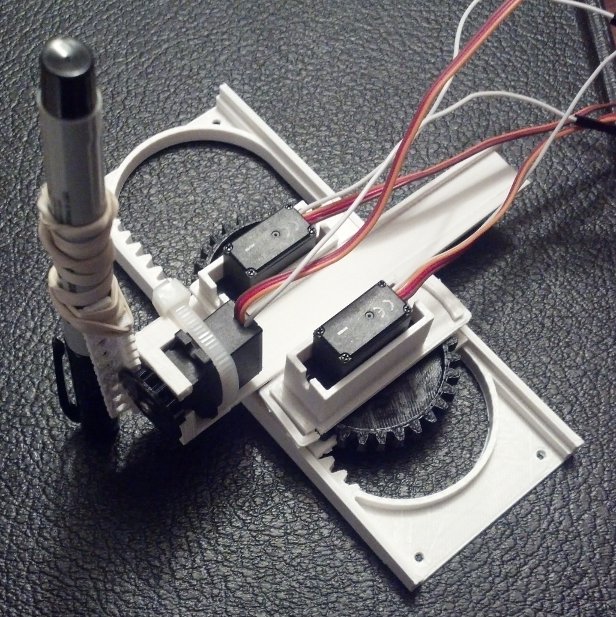
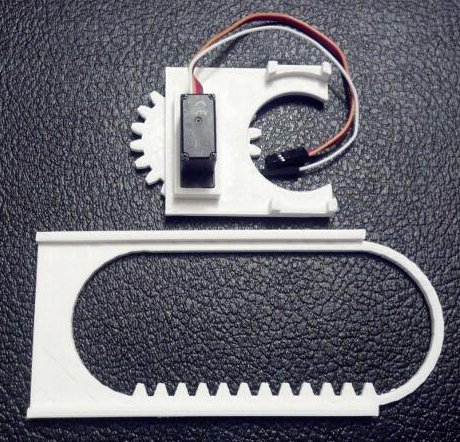
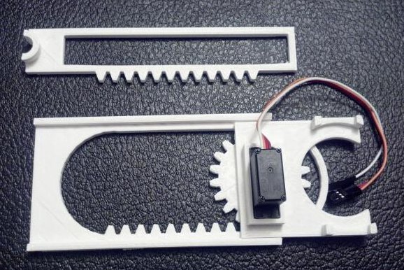
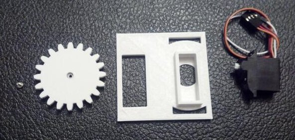
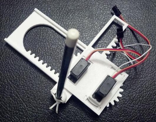
      1. Z axis.  My first attempt at printing a Z axis works.  The Z rack isn’t much more than a thin plank of plastic with a rack of teeth and some holes to help mount a pen or whatever to it – but, again, it works.
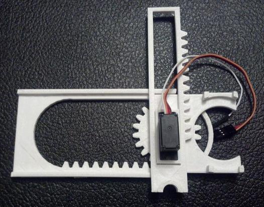
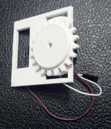
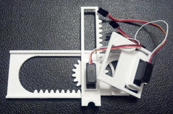
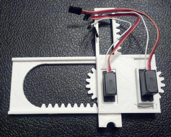
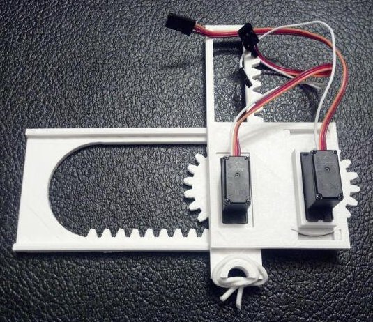
      2. Y rack and Y stage/motor mount.  The parts in this little robot are designed to fit/slot/snap together and lock themselves and each other into place.  I’m really really happy with how this designed worked out.  I basically entirely changed the entire method of securing the Y rack from version 0.18 to version 0.29.  In version 0.18 the Y rack slid along each side of the X motor mount.  In this version, it rides between the X and Y mounts, held in place by the Y pinion (gear), riding over the Y stage motor mount, and constrained by the X and Y motor mounts.  While not actually simple to accomplish, I feel like this was an elegant solution.  While I have some improvements planned for the next version, I don’t anticipate this changing at all.
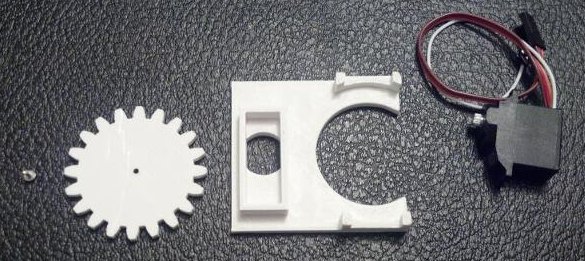
      3. Rubber band gaskets.  The problem with using printed pinions (gears) instead of the servo horns that come with the servos is that they don’t have the itty itty splines to mesh closely with the grooves on the servo motor gear.  As a result, no matter how hard you tighten down the servo motor set screw, the gear can twist away.  My method of dealing with this was to cut a small piece out of wide rubber band to use as a “gasket” between the set screw and the gear.  As you tighten down the set screw, it puts pressure on the rubber band and gear.  When the gear moves, the rubber band gasket prevents the set screw from rotating/sliding and loosening with use.
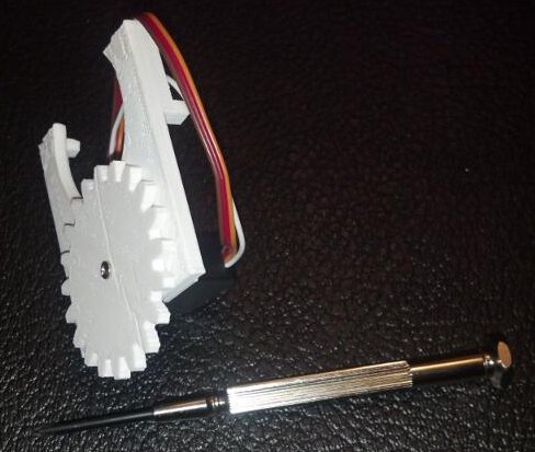
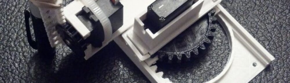
      4. Zip tie.  The zip tie on the Z motor seems to work very well.  I used a similar system for holding the servo in my PlotterBot pen holder.  The motor is held in place securely without much room for wiggling.  Although it is definitely possible to create a printable Z motor holder that doesn’t require any zip tie, the version I designed doesn’t require any overhangs.  I’m trying to avoid overhangs and support requirements in parts (which rules out all kinds of nifty groove/slide systems) so make everything easier to print and possibly easier for injection molding.
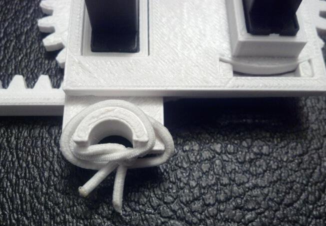
      5. Twist tie.  While not part of the directions or other documentation so far, I found a twist tie very helpful in controlling the sevo motor wires by bundling them together.
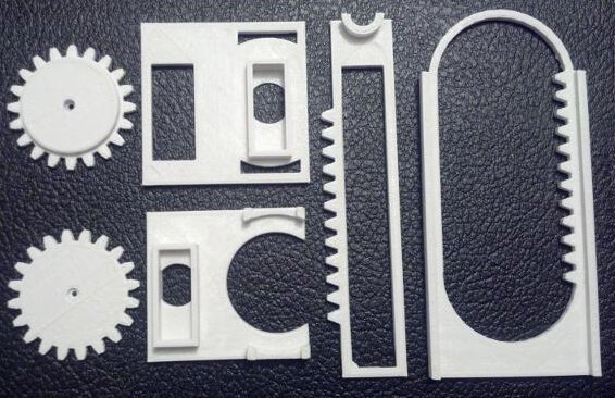
      6. Thinning and hollowing the XY pinions.  Since the most recent published version I made these big pinions slightly thinner and hollowed them out a little.  This theoretically reduces plastic a little.  Indeed, the 3-axis version of the robot actually uses less plastic than the 2-axis version I had uploaded a few weeks earlier.
    3. Here’s What Didn’t Work/Could Be Improved
      1. Rubber band gaskets.  These gaskets provide a drastic improvement for the gear’s ability to stay properly tightened on the servo shafts.  However, they’re not ideal since the rubber band gaskets just serve to create a little extra friction/traction between the set screw and the pinion (gear).  Now I’m trying something new that seems to work even better.  My daughter has these adhesive foam stickers in the shape of letters and animals.  For shapes with cutouts (like the letter “O”) the inside of the cutout is useless to her and is either found floating around the bottom of the bag or still slightly attached.3 I’ve place one of these between each of the set screws and pinions (gears).  The benefit of these is that they actually adhere to the surface of the pinion and actively resist being turned against the pinion. Another benefit of these is that they are thicker than a rubber band, so the set screw has to sink into them – creating more surface area contact between the “gasket” and the set screw.
      2. Y rack/Z motor mount.  I found that the zip tie for the Z mount interferes slightly with the Y rack slide.  I’ll need to raise the Z motor mount slightly to compensate.  Plus, I only just now realized there’s a slight overhang in this part I would like to eliminate.
      3. Z pinion.  The Z pinion includes a little flange to keep the Z rack in place.  The flange is a little too large and needs to be reduced slightly for easier operation.
      4. Z rack.  The Z rack isn’t much of anything, as mentioned above.  It’s just a rack with a plank with holes in it. It could be better refined to work as a pen holder without a lot of design work.  I just banged this one out so that I could have an actual no foolin’ 3 axis CNC to work with.  I have some ideas on how to make a simple pen holder.  Ideally, I would have two separate Z racks for this robot – one for holding a pen and another for use as an actual 3 axis CNC.
      5. Carriage tipping.  When the XYZ carriage has the Y rack extended as far out a possible, the weight of the extended Y rack with the Z motor and pen are more than enough to cause the entire XYZ carriage to tip out of the X rack.  This could be fixed by just creating a little guide, applying a piece of wire, or any number of minor hacks.  However, I’d like to have this issue resolved as part of the design of the robot.  Thus, I’m thinking of inverting the entire X rack to cause the X pinion to lock the X gear in place against the X motor mount.  The problem with this method is that it will basically require redesigning the X and Y pinions again.
    4. Anticipated Hardware Changes.  If I implement the improvements and changes I’m contemplating, this would mean redesigning the X rack (to invert it), X and Y pinions (to work with newly inverted X rack), Z pinion (to reduce the flange size), Z rack (to include a better pen holder). Y rack/Z motor mount (so the Z motor zip tie doesn’t hit the X motor mount), possibly Y motor mounts (to thicken the base slightly), and possibly the X motor mount to reduce plastic usage (since it wouldn’t have to be as big any more).  And… that’s a change to all 8 pieces.  :/
    5. Anticipated Software Changes.  Trinket space permitting, I would like to incorporate a small Gcode interpreter and fake USB serial connection.  I don’t know if this is possible, but I’d like to do this.  Also, my daughter specifically requested a 6-button interface to operate the robot.  I don’t know how to do this yet – but I’m willing to learn.  🙂  With three pins on the Trinket used for the three motors, there are only two pins left for buttons.  I’m pretty sure there’s no way to hook up a set of 5+ buttons to a Trinket and still have it operate all three motors.
    6. Fanciful Potential Changes.
      1. Keypad.  If this robot were to be powered by an Arduino Uno, you could probably incorporate this awesome 10-digit keypad from Adafruit to control the robot.  I think that would be a fun and accessible way for a kid to interact with this robot.
      2. Robotic Gripper.  With a fourth servo, a small robotic gripper hand could be attached to the Z axis – allowing this robot to do all kinds of interesting things.  It could be used to play chess, sort marbles, flip switches, or pick peas out of your dinner.

  1. And, again, these are perfectly acceptable tradeoffs given the size and price! []
  2. And, again, this is totally worth it []
  3. Much like a hanging chad []

How to Build a Tiny 3-Axis CNC Drawing Robot

Assembled Tiny 3-Axis CNC Drawing Robot

Assembled Tiny 3-Axis CNC Drawing Robot

FYI, if you like drawing robots and want to stay updated, please consider joining my newsletter.  Just stuff about drawing robots, no spam.

The Tiny 3-Axis CNC robot is a cheap, easy to build, extremely minimalistic but very capable little robot.1 This is the assembly guide for the version 0.29 robot available for download from Thingiverse.  The above picture shows the fully assembled robot.  If you have ever put together a lego set or built anything from Ikea, you should be able to build the entire robot in less than 5 minutes.  I’ve uploaded step-by-step photographs with each “step” organized into a short slide show of pictures.

This slideshow requires JavaScript.

Here’s everything you need to build your robot.

Stuff You Need

Tools

  • One small precision screwdriver
  • Scissors and/or wire cutters

Parts

There are eight plastic parts, one rubber band, one zip tie, and three micro servo motors.  Once the robot is assembled, you’ll need to wire it up to the microcontroller of your choice.  I’ll link to the wiring tutorial at the end of this post.

Assembly

Step 0:  Print the plastic parts

All 8 plastic parts

All 8 plastic parts

Although you can fit all 8 parts onto the build platform for a MakerBot Replicator 1, you’re probably better off only about half the files at a time.  I would suggest printing the five short pieces at once and the three tall pieces together.  All the parts together are about 30 grams of plastic and took my printer about 2.5 hours total.  I should point out that I incorporated thin little discs onto the corners of the larger STL files.  These are only to help the parts adhere to the build platform and fight warping.  You should be able to easily peel them off the pieces without any tools.

Step 1:  Build the Z axis

This slideshow requires JavaScript.

  • Gather the parts for the Z axis.  You will need three plastic parts (the printed Z pinion (gear), Z rack, and Z motor mount/Y axis), the zip tie, and a rubber band.
  • Use the scissors (or wire cutters) to cut a 5-10mm long piece out of the wide rubber band.  This piece of rubber band will work as a “gasket” to keep the Z pinion tightly secured to the Z motor shaft.
  • Push the screw through the rubber band gasket.  Place the Z motor into the motor mount.
  • Insert the screw (with gasket) into larger side of the Z pinion.  Insert the zip tie into the hole in the Z motor mount and secure the motor in place as show.  Try to zip tie your motor in a similar way – if you do it differently the zip tie can hit other moving parts.2
  • Cut off the excess zip tie with your wire cutters3
  • Place the Z rack as shown and secure the Z pinion in place using the precision screwdriver.  Rotate the pinion back and forth to make sure the Z pinion is placed well on the Z rack.
  • All done!

Step 2:  Build the Y axis

This slideshow requires JavaScript.

  • Gather the parts for the Y axis.  You will need two plastic parts (the printed Y pinion and Y motor mount) and another rubber band gasket.
  • Insert motor into motor mount and set screw into the gasket
  • Secure the Y pinion onto the Y motor using the set screw and you’re done!

Step 3:  Build the X axis

This slideshow requires JavaScript.

  • Gather the parts for the X axis.  You will need three plastic parts (the printed X pinion, the X motor mount, and the big X rack) and another rubber band gasket.
  • Insert motor into motor mount and create another screw-gasket-pinion combo
  • Secure X pinion to the X motor using the set screw
  • Looking at parts from top, rotate the X pinion counterclockwise until it stops and place it on the X rack as shown.  Roll it back and forth to make sure it stops at either end.  If it stops in the middle, just pluck it out and move it to where it needs to be.

Step 4:  Put it all together!

This slideshow requires JavaScript.

  • Gather the Y and Z axes.  The Z axis is basically the same part as the Y rack.4
  • Looking at parts from top, rotate the Y pinion clockwise until it stops. Insert the long flat “fin” on the Y axis through the thin slot in the Z axis.  The Y pinion teeth should mesh well with the Y rack.5 Make sure the Z axis is as close to the Y axis as possible.  Roll Z axis back and forth to make sure it stops at either end.  If it stops in the middle, just reposition the Z axis to where it needs to be.
  • Gather the X axis.
  • Route the X motor wires through the hole in the Y axis “fin.”6
  • Pressure fit the YZ axis assembly onto the X axis.  Make sure the Y axis isn’t too tight on the X pinion.

Step 5:  Add something to the Z axis

Pen secured to Z axis with rubber band

Pen secured to Z axis with rubber band

This Tiny 3-Axis CNC is designed to be a platform for you to turn into anything you want.  Personally, I think it would be most fun as a tiny drawing robot.  If that’s your interest too, you could use a rubber band or zip ties to secure a pen to the Z rack.  However, there’s no reason you couldn’t use it to perform any number of tasks.  A fully functional Z axis allows the little robot to actually apply pressure to the drawing surface – making crayon drawings feasible, painting with brushes, some kind of automatic pin-pricking machine, or a gentle tickling robot.  By adding a fourth servo motor you could add a robotic gripper, automated syringe/plunger/eyedropper, or something else so entirely amazing that no one has thought of it yet.

Step 6:  Wire the robot to a brain

If you want to use an Arduino, I’ve already written a guide on how to run your DIY drawing robot to a variety of Arduino boards.  However, there’s no reason you couldn’t run this robot from any other kind of microcontroller or computer provided you figure out a way to operate servos with those devices.

Step 7:  Program your Tiny CNC drawing robot

Okay, confession time.  I don’t have any software to offer you … yet.  As I write this post, my first Tiny CNC design isn’t even 30 days old and is being improved upon and changed quickly.  Fortunately, at least two other fine persons have already contributed to this area.

Stephen Laporte has written some software to run an XY version of this robot.  Additionally, Thingiverse citizen Oliv4945 has created a Gcode interpreter just for the XY version of the Tiny CNC.

Room for Improvement

Even though this design is only a day old as I write this post, I’ve already got lots of ideas on improving it:

  • Pen Holder.  I want a better Z rack that is specifically designed to work as a pen holder.  I will always offer a non-pen-holder version so people can use this robot as a 3-axis CNC to do their7 bidding.
  • More Secure Drawing.  A redesign of the X pinion and X rack.  Right now the entire XYZ carriage can pop out of the X rack if the robot meets too much resistance.8  I have an idea to fix this problem completely.  If it works, the robot could be bolted mounted vertically or upside down and still work just fine.
  • Reducing plastic.  Interestingly, I reduced the amount of plastic in the design from version 0.18 to version 0.29 even though I added an entire additional axis.  The plastic could be reduced by thinning some parts and adding holes to other parts as The NewHobbyist did.  The interesting thing about “holes to reduce plastic” is that the actual “savings” may be illusory.  With 3D printed plastic parts adding holes to a design can significantly increase the amount of plastic used – when you’re printing at less than 100% infill. As a thought experiment, think of two plastic cubes with a 1mm thick wall around all surfaces.  One plastic cube has no holes and is printed at 10% infill.  The second plastic cube is also printed at 10% infill – but because it is riddled with holes that require a 1mm wall around every hole, there  is basically no space for the 10% infill.  The “holes to reduce plastic” trick only works on 3D printed parts that are thin pieces.  When it comes to parts that are injection molded, it’s my understanding that additional “holes” all the way through a part adds to the design complexity and can increase tooling costs.  That said, it would actually result in a reduction of plastic in a design.
  • Electronics.  For a variety of reasons, there isn’t one particular electronics/microcontroller solution that strikes me as the “best.”  ((That said, the Adafruit Trinket is ALMOST perfect for this job!))  For this reason I’ve considered possibly designing a tiny Arduino board with three or four servo pin-outs specifically for this robot.
  • Software.  I have some ideas on this and a heck of a headstart from Stephen and Oliv4945.  🙂
  • AFRON UAER Challenge.  If you haven’t heard about it, African Robotics Network (AFRON) has a new Ultra Affordable Educational Robot (UAER) design challenge this year.  They’ve also extended the submission time for the 2013 challenge to January 15, 2014.  With some creative sourcing and scrounging, I think I could bring the “cost” of this robot down to $10-$20.  This is a somewhat artificial goal since the “cost” as far as the UAER does not include shipping, taxes, tools, packaging, computing, and is based on the proportional cost of bulk-pricing.  I think I could enter this robot into the hardware, software, and community challenges.  I don’t have enough experience designing educational curriculum to outline the 20+ hours worth of material necessary to enter the curriculum category of the challenge.

If you’ve enjoyed this post, perhaps you’d consider donating a +1 to my WyoLum Innovation Grant challenge entry.  🙂

  1. Smaller than a paperback novel!!! []
  2. It won’t damage anything, but it will be a nuisance! []
  3. This is where they really come in handy []
  4. I know, the teeth are a dead giveaway []
  5. AKA Z axis []
  6. I really need to think up a better name for that design feature []
  7. Very tiny []
  8. RESISTANCE!!! IS!!! USELESS! []

Tiny CNC – An Experiment in Commerce

Dolla' dolla' bills, yo'

Dolla’ dolla’ bills, yo’

I tried a little experiment last weekend.1 I listed the plastic parts for Tiny CNC version 0.18 on eBay.  I did this for a number of reasons:

I really wanted to see someone else put together this robot.  Also, getting rid of my only set of parts would basically force me to design and print new parts if I wanted to start another drawing.  Lastly, I was genuinely curious whether anyone would actually be interested in purchasing parts.  If there was enough interest, I might be able to turn this into a kit to get more robots in more peoples’ hands.  If I made a little profit in the meantime, then great.  The auction had six bidders with nine total bids, ending at $13.63 plus $4.00 for shipping, for a total of $17.63.

But, what’s an experiment if you don’t share the results?

  • The eBay auction for the one-and-only set of plastic parts for version 0.18 I’ll ever sell ended after three days.  The gentleman who purchased them made an immediate payment and I was able to swing by an office supply store, buy a padded envelope, leave work early for my house to pick up the parts, and then the post office to drop them off.  I tossed in the parts from version 0.14 as well since I’m not going to use them and he might get some use from them.  I received a very nice email from him today letting me know they arrived.
  • Here’s the breakdown so far:2
    • Plastic parts:  2.5 ounces, or 70.9 grams, of white MakerBot ABS plastic.  This plastic is $52.08/kg, inclusive of shipping.  This comes to $3.70 in plastic which took about 2 hours to print.
    • Padded envelope:  $1.62
    • Postage:  $4.77 total
      • Postage was $2.07 for the 2.6 oz package, first class, large envelope
      • I accidentally bought signature confirmation for $2.70 rather than tracking for only $0.90.  So, rather than the total being $2.97, it was $4.77.  D’oh!
    • Three sheets of paper:  $0.18
      • I printed out the eBay auction, used a piece of paper to separate out the old version 0.14 parts from the version 0.18 parts, and a third sheet of paper to print the addresses
    • eBay fees:  $1.76
      • Actually, by a total fluke, I happened to list this item on a day when there were no eBay fees!  Some sort of Black Friday promotion.  I didn’t even realize this until I went back to track down the eBay fees for this post.  I’m listing the fees here so I can get an accurate read on the cost of listing these parts on eBay.
    • PayPal fees:  $0.81
    • Total eBay payment:  $17.63
    • Total costs:  -$12.84
    • Net profit:  $4.79

At a “profit” of $4.793 this wasn’t exactly lucrative.  I’m pretty sure I’d also owe taxes on this “profit” too.

The parts took about 5 minutes of setup, 2 hours of unsupervised Replicator printing time, about 5 minutes of sanding for a better fit,  and let’s say about 30 minutes of time to package and ship.  This doesn’t count any of the amount of time spent on development4 , listing parts for sale5 , or telling people about the sale.6  At less than $5 for all that work, this isn’t really worth anyone’s time.7

Fortunately, 100 kits doesn’t actually take 100 times the amount of time.  So, it remains possible that at a certain volume this becomes feasible to produce as a kit.  I figure the advertising time for a bunch of kits would be a lot higher8 but less than 100x the time spent advertising this first set, the time spent on assembling/packing/getting ready for shipping would be about 100x, and the time spent actually shipping would be about the same as the time to ship one copy.9

More on the economics of kits in the next post…

  1. Photo courtesy of donbuciak []
  2. For the time being, I’m excluding gas, mileage, electricity, wear and tear on my 3D printer, and the value of my time []
  3. I would have made $6.59 if I hadn’t screwed up the postage – but there you go! []
  4. 10 hours? More??  I had to update an OpenSCAD rack/pinion script, and developed versions 0.1 through 0.14 before I had something to print. []
  5. 30 minutes – it’s been a long time since I’ve sold anything on eBay []
  6. An e-mail to the newsletter, a two tweets, revising the Thingiverse post to show the parts were for sale []
  7. Less than $5 for  1 hour of work is well below minimum wage []
  8. More tweets, better copy, a video demonstration []
  9. Since I’m hoping it would take about the same amount of time to drop off one set as it would 100+ sets at the post office []

Uses for a Tiny CNC Robot

Thinigiverse user Zamanlui's copy of a  Tiny CNC

Thinigiverse user Zamanlui’s copy of a Tiny CNC

Thinigiverse user Zamanlui printed a Tiny CNC with the idea to turn it into a platform for a phage/bacteria printer. While I realize that a two-axis CNC machine can be used for just about anything, I LOVE the idea that something this easy and cheap to build could be put to such noble uses.1 This makes me wonder…  what other potential uses would there be for a simple low cost CNC machine?  Here’s what I have so far:

  • Phage/bacteria printer
  • Drawing robot (one-off business cards, playing Tic-Tac-Toe, etc)
  • Drawing electronic circuits with a conductive ink pen2
  • Adding a third servo for a Z axis and a fourth servo for a gripper for a tiny sorting robot
  • I guess you could turn one into a useless machine that turns itself off?
  • Automatic pencil sharpener?

What other ideas can you think of?

  1. Especially when my most noble idea is to make the ‘bot cheat at Tic-Tac-Toe []
  2. How awesome would it be to use a Tiny CNC to draw an electronic circuit used to power a Tiny CNC?! []

Better video of Tiny CNC Drawing Robot actually drawing

I wanted to share a video of the ‘bot in action that was slightly less terrible.  In this one I’ve elevated the robot on two stacks of index cards, taped it down to keep it from wandering off, and given it a pen to draw with on another 3″x5″ index card.

I elevated the robot for two reasons.  First, it allowed the ‘bot to have a better “grip” on the pen (rather than just holding it near the tip) and resulted in a much better drawing.  Secondly, I’m using an old version of one of the gears which extends slightly below the larger rail due to the set screw.  By elevating the ‘bot, the screw doesn’t hit the surface and cause a wobbly walking motion.

The other day I discovered that I could use the Adafruit FTDI Friend to provide power to the Mintduino as well as reprogram it.  All I had to do was run a little red wire from the VCC pin to the positive rail and a black wire from the GND pin to the ground.  Easy!  Since then I’ve abandoned powering the Mintduino by 9V battery.  🙂  The next time I find an old USB mouse or keyboard, I’m going to definitely clip it’s leads so I can turn it into a USB source of 5V power for projects.  It’s convenient to use the FTDI friend to reprogram and power the board, but it’s a little awkward and not a great permanent solution.

How to Build a Tiny CNC Drawing Robot

Tiny CNC - all the parts needed

Tiny CNC – all the parts needed

UPDATE: Here’s everything you need to to build a Tiny 3-Axis CNC robot using just 8 plastic pieces.

The above are nearly all the tools and parts you’ll need to build your own itty bitty CNC drawing robot.1 If you have a 3D printer and a spare Arduino, the rest of the parts should cost you around $20.  Right now this robot only has two axes, but in the very near future I hope to add either a Z axis or a pen lift.  Without further ado the tools needed are:

Tools

  • One small precision screwdriver

Parts

You’ll also need an Arduino, some wire to connect your servos to the Arduino, and a USB cable to communicate with the Arduino.

Assembly

Step 1:  Print parts

All printed parts

All printed parts

There are only six printed parts necessary for this mini-CNC.  If you’re careful, you’ll be able to fit all six on your MakerBot Replicator into a single build plate.

Step 2:  Assemble the X axis stage

step04

Grab your Micro Servo, the little screw that came with it, the flat gear (really, pinion), and the X axis stage.  Just insert the Micro Servo into the X axis stage (it only fits one way), push the gear onto the Micro Servo’s motor shaft, and use the screw to secure the gear.  It should look like this when done:

Assembled X axis stage

Assembled X axis stage

Step 3:  Place the X axis stage on the large X axis rack

X axis stage and X axis rack

X axis stage and X axis rack

With the X axis stage gear-side down, rotate the gear clockwise until it stops.

X axis stage and X axis rack

X axis stage and X axis rack

Then place the gear into the X axis rack as show.

Step 4:  Place the Y axis rack

Y axis rack

Y axis rack

Locate the Y axis rack and place it over the X axis Servo Motor.

Y axis rack in place

Y axis rack in place

Like so.

Step 5:  Assemble the Y axis stage

Building the Y axis stage

Building the Y axis stage

Just as with the X axis, gather the parts and assemble.  This time, the servo motor goes into the stage (it only fits one way), the thick gear is then pushed onto the motor shaft with the gears toward the Y axis stage.

Assembled Y axis stage

Assembled Y axis stage

Like so.

Step 6:  Add the Y axis stage

With the Y axis stage gear-side down, rotate the gear clockwise until it stops.

Getting the Y axis stage ready

Getting the Y axis stage ready

Route the X axis servo motor wires through the rectangular hole in the Y axis stage.

Routing X axis servo motor wires through the Y axis stage

Routing X axis servo motor wires through the Y axis stage

Place the Y axis stage down, with the large rectangular hole around the X axis motor.

Almost done building a robot!

Almost done building a robot!

Almost done!

Step 7:  Ready the pen holder

Place the rubber band around the pen holder as shown.  You will probably have to wrap it around a few times.

Rubber band wrapped pen holder

Rubber band wrapped pen holder

Insert a pencil, pointy-bit down, into the pen holder.

Full assembled drawing robot

Full assembled drawing robot

Step 8:  Admire your work

A baby robot is born!

A baby robot is born!

Your robot is done!

Step 9:  Wire Robot to Arduino

To save you a little bit of trouble reading the Arduino sketch and figuring it out, here’s how you would connect your robot to the Arduino:

  • Use a piece of wire to connect the orange wire from the bottom X axis servo to pin 13 on the Arduino
  • Use a piece of wire to connect the orange wire from the top Y axis servo to pin 12 on the Arduino
  • Connect the brown wires from the servos to the ground pins on the Arduino
  • Connect the red wires from the servos to the 5v pin on the Arduino

Step 10:  Draw!

Download my Arduino sketch to operate this robot.  The movements of the robot are hardcoded at the moment, so please check back for updates.  Also, if you don’t tape or glue or somehow affix the little bot to a heavy surface, it will literally jerk itself all around the table.  (Although, in retrospect, I could have made it draw slower…)

It’s a little difficult to see the lines as the robot is drawing, but it really is drawing a grid in this short video:

Room for Improvement

I hacked this little project together just in time for the MAKE and GE Robot Hacks presentation on 11/20/2013, so I know there’s lots of room for improvement.  Here are some things I’m working on:

  • An entire Z axis or pen lift mechanism using a third servo
  • A better pen/pencil holder
  • Actual code to use XY coordinates instead of directly specifying the degrees for each servo
  • Actual motion control software from Processing or Python
  • A few adjustments to the Y axis stage for a better fit
  • Possibly thicker gears so that I can use set screws
  • A variation on the gears to use less plastic
  • Getting the robot to work with my Adafruit Trinket!

I hope you enjoyed this quick to print and easy to use desktop drawing CNC!

  1. You’ll also need an Arduino and some bits of wire []

An Itty Bitty Drawing Robot

OpenSCAD Rendering of Mini CNC

OpenSCAD Rendering of Mini CNC

My daughter and I recently signed up to take part in Make’s Robot Hacks’ project.  Make was kind enough to send me a box of parts, including the Make Ultimate Microcontroller Pack and a bunch of servos.

The catch?  We had to actually create something and share my progress by November 20.  From the time my parts arrived, this was exactly 14 days.  🙂

I had a number of ideas about what I wanted to make – an automated Robo Hand, electronically released spring loaded wings, a little servo-powered walking robot, and a dozen of other smaller ideas.  My daughter’s ideas were significantly more ambitious – flying, wall crawling, dancing, hearing, seeing, talking, thinking robots.12 The idea that I kept coming back to was a tiny little CNC robot using servos powered by an Arduino – something I had first seen in February of 2012 with Piccolo – the tiny CNC-bot by the Diatom Studio team.

My adventures building robots aside, I still consider myself a “newb.”  However, I knew the basics of what I needed to accomplish:

  1. Drive three servos with a single Arduino
  2. Make each servo drive an axis of movement
  3. Figure out a way to translate 180 degrees into linear movement

So, for what it’s worth, here’s my process:

Driving Multiple Servos with a Single Arduino

Since I had never (!) driven a servo with an Arduino, I needed to figure out how to manipulate at three servos at the same time.  Fortunately, the Arduino “Sweep” example explicitly states that it’s capable of controlling eight servos.

Connecting them was significantly simpler than I was anticipating.  For the Batan B2122 servos I had, the brown wire was ground, orange wire was positive, and yellow wire was the “control” that would have to be connected to one of the Arduino’s digital out pins.3 The easiest way for me to wire up the three servos was through a small breadboard.

Once the servos were wired up, it was a matter of loading up the Sweep example and driving a single servo back and forth.  By adding a few lines, I was able to drive two servos, and then three.

Using a Micro Servo Motor to Drive an Axis of Movement

The Batan B2122 micro servos are not continuous rotation motors – they only have a 180 degree range of movement.  Most CNC machines use stepper motors which are strong, fast, precise, and can rotate continuously forwards or backwards.  Servo motors, by contrast, are smaller, cheaper, slower, and unless they are specifically designated as “continuous rotation” have a limited range of movement.

I considered two different ways, each with their own merits, of using a limited range of motion motor to drive an axis of movement.  The first way I considered was using a spool and twine to drive each axis – similar to the Printrbot Simple and WaterColorBot.  This is an excellent and cheap alternative to using expensive precision toothed belts to control movement.  The reason I didn’t use this method is that it would have required a spool for the twine, and some form of rails or metal rods, and of course twine.  My concern is that this would have been a bulky solution for such a small robot.

The second method, the one I decided upon, was to use a rack and pinion to turn the rotational motion of the servos into linear motion.  One benefit of using a rack and pinion is that the rack itself removes the need for rails or precision rods, spools, and twine – all while providing a sturdy framework for adding additional axes.

Translating 180 Degrees into Linear Movement

As I alluded to above, the micro servos only have 180 degrees of movement.  Thus, a gear (or pinion) attached to a servo would only be able to drive the rack by 1/2 of its circumference (or 180 degrees).  Keeping that in mind, I chose a gear size that would produce the desired freedom of movement.  I settled on a gear radius of about 20mm because it created about 2.5 inches or 62.8mm [ (2 * π * 20)/2 = 62.8 mm] of movement.

Moving a pen over a 2.5″ square would enable me to create nifty little robo-drawn post-its, bespoke business cards, or an auto-signature device.

Here’s what I have so far:

Next Steps…

Since the robot isn’t actually capable of doing a whole lot yet, I’ve got a bit to do still:

  1. I need software to interpret XY coordinates or GCode into rotational degrees
  2. Get write a Processing or Python script to send the XY coordinate or GCode to the Arduino
  3. Slightly redesign the two gears (well, pinions) so that it’s easier to attach them to the servos
  4. Create a new Y rack that can hold the third servo (for the Z axis) and a pen for drawing

Since I’m only intending to use this little CNC for small drawings, I don’t really need a huge Z axis lift – even a few millimeters should be sufficient.  I was considering cheating a little and just making the “Z axis servo” just lift the front of the robot off the surface.

Even though I’ve got a bit of work ahead of me, I’m pretty happy to have a working proof of concept of a robot of my very own design!

If you would like a little robot like this of your very own, you can find my 3D printable files on Thingiverse and the Arduino code is pretty much the stock “Sweep” example.  Stay tuned because I’m looking forward to turning this into a legit itty-bitty CNC drawing robot.

  1. Just put the words on a microchip and put the microchip in the robot’s head, Daddy []
  2. Thanks pumpkin! []
  3. If this seems like Greek to you, as it did to me just a few weeks ago, I’d recommend picking up a Mintduino kit and blinking a single LED.  You’ll be able to blink two LED’s in no time! []