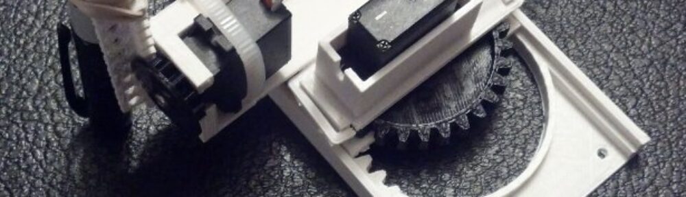

Intermediate version with minor design changes
Above is a picture of the most recent version of this robot. It includes two nifty changes and one design aspect ((The Y axis)) that will probably involve me using design elements I had discarded earlier. Here’s what I’m working on:
- No tools.
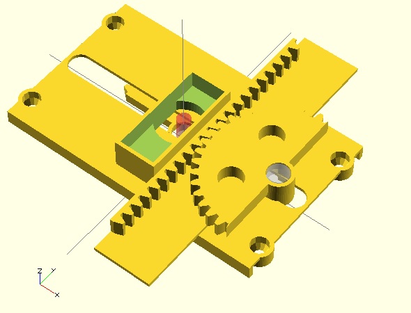
- The problem with using set screws to affix printed gears to the servos is that too little tightening means the gears will slip ((Even with foam rubber stickers!)) and too much tightening will strip the micro servo gears almost without warning. ((There’s a slightly sickening crunch as you do. I don’t recommend it)) I’ve redesigned the pinions (gears) so that you can just push the servo horn through the gear and then push it onto the servo gear. If you wish, for smoother and more reliable operation, you can always add the servo set screw to the servo horn, but it isn’t necessary. Best of all, you’re not going to strip your micro servo gears when you do this.
- This design did not come without concession. I had to compromise on my ideal of removing overhangs. All published parts to date have been printable with completely flat bases and without even slight overhangs to improve and ease printability. In order to create the smaller pinion above, I had to add an overhang. However, it’s a short overhang, which should still easy enough for most printers.
- Redesigned motor mounts. I’ve changed the motor mounts so the fit the ((Many, many)) micro servo motors I purchased. Hopefully they’ll fit yours too. 🙂
- Improving the X axis.
- I’m reasonably happy with the X axis. It’s not idea – but it works. I’m designing a way to invert the X rack, so it is trapped by the X pinion and the entire robot can stay together. This is still in an early design stage and so far requires lots of other design changes, so I’m trying to solve the Z axis and Y axis problems before working my way out to a better X axis.
- Improving the Y axis.
- The problem. The Y axis I created for the version 0.29 steady as the the Y axis in the version 0.18. With the earlier version the Y axis slid on either side of the X motor mount, so that it was difficult for it to wobble side-to-side. The newer version only slides along one side and incorporates this a long “fin” intended to stabilize the Y axis’ side-to-side motion. That “fin” also had a long groove in it that was designed to help with up-and-down motion stability. I think it worked for the most part. In reality, the Y axis can wobble as much as a 1-2mm to the left and right in the new version. One of the reasons I moved to the system used in the version 0.29 is that it allowed me to place all the motors in a very compact area while keeping the Y axis relatively short. This conserved plastic, kept the part sizes small, and kept most of the mass in the robot in one area – which I felt would help reduce wobble.
- The solution?
- One obvious route is to go back to the Y axis alignment system used in version 0.18, where it slid along both sides of the X motor mount. I moved away from this system because there didn’t seem to be a good way to mount the Z motor. Not having a really great solution to mounting the Z axis motor isn’t that big a deal. The current motor configuration is reasonably symmetrical and aesthetically pleasing, but not critical by any means. As long as the robot isn’t operated at ridiculous speeds, the unsymmetrical motor mounting shouldn’t be that big of a problem. While I have another design option, I think this is the system I’ll end up using.
- The other option is to cut a long groove in the Y axis with a tab sticking out of the X motor mount ((This makes more sense if you’re inside my head)) to keep it steady. As the Y axis slides back and forth, it should be kept in line by the tab. Similar to this, I could also put a groove in the X axis where the Y axis slides to keep the Y axis in line.
- Improving the Z axis.
- The Z axis is a little wobbly. While a little wibbly-wobbly-ness is to be expected, when there’s a little introduced with each axis, the effect is compounded in the end result. This isn’t a problem for large gross manipulations, but becomes more obvious when drawing. One of the reasons I’m tuning this robot to draw well ((As well as can be expected for a bunch of plastic parts and cheap motors)) is that if it can draw well, chances are it can do other tasks well too.
- Improving the X axis.
- I know this isn’t in any obvious order. 🙂 However, I’m reasonably happy with the X axis. It’s not idea – but it works. I’m designing a way to invert the X rack, so it is trapped by the X pinion and the entire robot can stay together. This is still in an early design stage and so far requires lots of other design changes, so
- Things to try out.
- Drawing without pens. Recently the idea occurred to me that drawing with a pen may not be ideal. A pen is designed for the human hand – so it has heft, grip, length, and all sorts of other attributes that aren’t ideal for a robot. However, the pen cartridge/ink reservoir is shorter and has considerably less mass. So, why not just pull that out of a pen and scrap everything else? Heck, there might even be an interesting way to incorporate the pen’s own spring into the design. I think it would be incredibly interesting to use that spring as the basis for a pen holder. ((I’m not sure if this would be cannibalistic or meta. Thoughts?))
- Smaller, more numerous teeth. I honestly don’t know if these are beneficial. I’m guessing there’s a law of diminishing returns when it comes to using smaller teeth. Smaller teeth are harder to print and may be easier to break or more prone to skipping. On the other hand, it is possible they might allow for smoother and more reliable operation. I’ll try it both ways and let you know!
- Closer meshing between pinions and racks. I’ve designed the robot with a degree of “slop” between the pinion and rack teeth. This is so that I can make parts that I know will fit and work on many different robots. I like to think I’ve got my Replicator 1 dialed in pretty well – so it’s entirely possible I could place the teeth closer together. I figure closer meshing probably involves more stress on the motors, but that’s another problem for another day and another blog post. 😉
- Designing with fasteners in mind. One interesting solution from Joseph is to put zip ties around the various parts to keep them in place. The zip ties are apparently smooth enough that the parts still slide and stay together. I love this solution. I think it could be even better if zip tie solutions were further incorporated into the design as fasteners.
- Putting it all together. The new-ish design you see at the top allows for the use of servo set screws without actually requiring them. They’ll help, but aren’t critical.