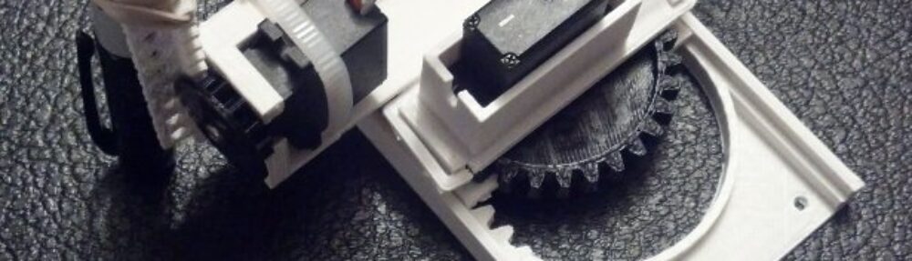
New possible design direction for the Tiny 3-Axis CNC
I find myself at a design crossroads, as it were, with the Tiny 3-Axis CNC. There are certain improvements that I think are necessary to make the overall robot more functional and reliable. However, to adjust these designs to accomplish these improvements would require a compromise of some part of the design ideals I’ve been employing so far.
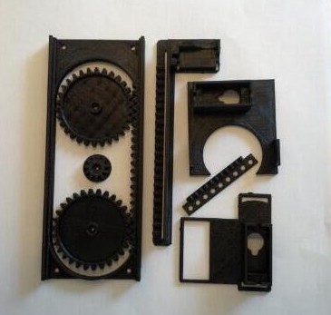
One unintended consequence of having a low number of interlocking parts is that when I make a design change to one part of the robot, the design implications ripple throughout the rest of the robot. Thankfully, this is made slightly easier by using OpenSCAD which automatically adjusts parts depending upon changes to variables. These changes also have the side effect of making each version of the robot unique enough that almost no parts are compatible with other versions. As a result, I’ve got a pile of parts from intermediate non-functional versions which don’t really work with any robot version.
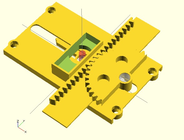
In order to overcome some problems with the last design ((Principally the XYZ carriage tipping out of the X rack)) , I basically now need to choose what I value most:
- Elegance. Design elegance is a very murky and personal topic. I think of design elegance as incorporating the fewest possible number of parts, simplicity, and (when possible) symmetry or the reuse of parts. Even “simplicity” is a convoluted and subjective ideal. I think of this as the least amount of plastic and least amount of complex features.
- Low Part Count. I love the idea of a super low part count. If I were to print parts with support structures or had a very complex design for injection molding, I could probably reduce the part count to the absolute bare minimum possible number of parts – 7. ((I think this would require: the X rack/base, the X pinion, X motor mount, Y pinion, Y rack, Z pinion, and Z rack.)) However, if I try to make the parts easily printable without overhangs or support structures I have to increase the number of parts.
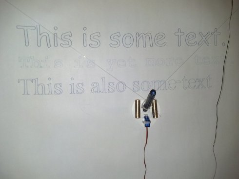
- Easy to Print. Even if a 3D printer is capable of printing with mild overhangs and support structures, a design is more easily printed if it doesn’t include such features. It is very important to me that the parts are easy for people to replicate on their own. For me, part of being “easy” to print is having as little plastic as is required. The most recent stable version of this design takes about 2 hours of printing on my Replicator. I think I can do better.
- Easy to Assemble. Generally, I’ve found the more complex and numerous the parts, the more difficult and less intuitive a thing is to assemble. I would really like this robot to be able to be assembled by my 6 year old with minimal adult intervention. She’s pretty good at building Lego designs from the graphical instructions and I’d like to have something similar here. Fortunately, OpenSCAD make it really easy to create Ikea/Lego style graphical assembly instructions.
After discussing these issues with some friends, I think I’m going to sacrifice the super low part count as I push the design forward. I don’t anticipate this will cause the design to have a higher plastic content – just a few more pieces. Overall, if I had to sacrifice one particular design ideal in order to adhere more closely to the others, I would have to choose the super low part count. After all, I could always publish an additional version that combines two or more parts into a version that could be printed with support structures. 🙂
Default Series Title