How to Wire a Tiny CNC

Easier than this to wire up

Easier than this to wire up

Don’t you just hate it when you read an online tutorial shows you how to build something – but totally glosses over how to wire it up?1 Me too.  Fortunately for you, dear reader, I’m not going to let that happen to you.  Not today, my friend, NOT TODAY.

The Basics

A few weeks ago I knew next to nothing about how to do anything with an Arduino and least of all how to wire one up.  Even though people had told me it was easy, I couldn’t make much sense of Arduinos except to load sketches I had downloaded.  Here’s some of the stuff I would loved to have known:

  1. Arduinos have a bunch of “pins” that can act as either inputs or outputs.
  2. When you program the Arduino, you tell it whether a pin is supposed to be an input or output.
  3. When the Arduino uses a pin as an “output” it can send a little bit of power to that pin.  That’s enough power to run an LED and maybe a small motor, but not enough to do a whole lot.  For things that require more power, you have to get it power from elsewhere.
  4. Arduinos have little “power regulators” that take power up to 12v and bring it down to 5v so the Arduino can use it without getting crispy.
  5. You can tap into that 5v power line to use for the things that require more power than the output pins provide – but if the things you connect to the 5v power line draws too much power, it can make the power regulator get… crispy.  🙂

Okay – that should be enough to get us started!

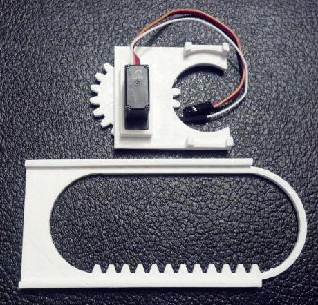
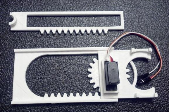
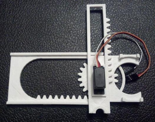
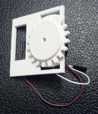
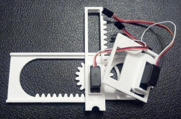
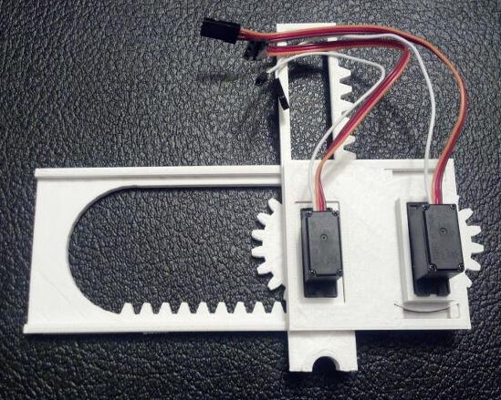
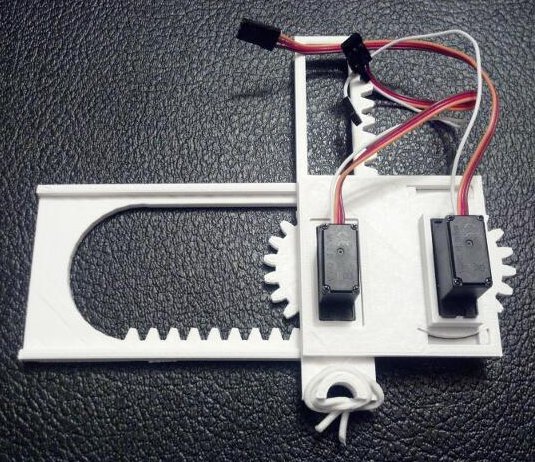
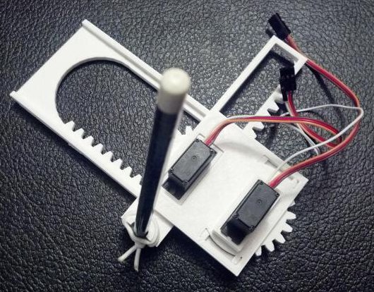
Wiring the Tiny CNC to a Mintduino

The easiest “out of the box” solution for wiring the Tiny CNC is with a Mintduino.  The Tiny CNC has two (soon to be three) servos that have three wires – a positive wire, a ground wire, and a control wire.  Each of the servos will need to have power sent to the positive wire, the ground wire grounded, and the control wire connected to an output pin on the Mintduino.  The reason the Mintduino is the easiest solution is it has a breadboard which is a very simple way to connect all the servos’ wires without a lot of fuss.

Here’s how we do it:

This slideshow requires JavaScript.

  1. Build the Mintduino.
  2. Bring power from the programming pins to the board.  Use a piece of red wire to connect the red positive rail to “a28.”  Now when you connect the FTDI Friend to the Mintduino, it will be ble ot draw power from the USB cable.
  3. Add two 3-pin male headers to the breadboard – one on “i23, i24, i25” and one on “i26, i27, i28.”
  4. Using a red wire connect 5v power from the red positive rail to “i24” and “i27.”
  5. Using a black wire connect the ground rail to “i25” and “i28.”
  6. Connect the Arduino output pins of your choice (I used 12 and 13 here) to “i23” and “i26.”
  7. Connect one servo to “i23, i24, i25” with the brown ground wire connected to “i25,” center red positive wire connected to “i25,” and the orange control wire to “i24.”
  8. Connect the second servo to “i26, i27, i28” with the brown ground wire connected to “i28,” center red positive wire connected to “i27,” and the orange control wire to “i26.”
  9. Connect the FTDI Friend to the Mintduino with the USB port side facing the connectors for the servo.

Wiring the Tiny CNC to an Adafruit Trinket

The basic setup here will look pretty familiar to the breadboard from the Mintduino.  Heck, I’m even using the itty bitty Mintduino breadboard in this example.

This slideshow requires JavaScript.

  1. Add two 5-pin male headers and three 3-pin male headers to the breadboard.
  2. One 5-pin header should be placed from “d4” to “d8” and another from “g4” to “g8.”
  3. One 3-pin header should be placed from “i9” to “i11,” a second from “i13” to “i15,” and a third from “i17” to “i19.”
  4. Use a red wire to bring the power directly from the USB on “g4” to the red positive rail.  Do NOT bring the power from the pin marked “5v” at “g8” because that pin draws the 5v through the Trinket’s power regulator rather than directly from the USB line.
  5. Using red wires bring the 5v power from the red positive rail to the three servos at “i10,” “i14,” and “i18.”
  6. Use a black wire to bring the ground from the Trinket on “c4” over to the black ground rail.
  7. Using black wires to bring the ground from the ground rail to the three servos at “i11,” “i15,” and “i19.”
  8. The Trinket can operate up to three servos from pin 0, pin 1, and pin 2.  Connect pin 0 at “h5” to “j9,” pin 1 at “h6” to “j13,” and pin 2 at “h7” to “j17.”
  9. Now drop the Adafruit Trinket in place as shown and you’re good to go!

Wiring the Tiny CNC to an Arduino Uno

I’ll take the pictures and update this part soon, but wiring the Tiny CNC is pretty easy too – as long as you have a breadboard.  Just follow the steps for the Trinket above, but bring the power from the “Vin” pin to the red positive rail and the ground from one of the “GND” pins to the black ground rail.  This will provide the power and ground for the servos.  Now you need to do is connect three pins (say 11, 12, and 13) to the three control lines for the servo at “j9,” “j13,” and “j17.”

Okay!  That’s it for the wiring!

  1. Photo courtesy of Peter Kaminsky []

Tiny CNC – Going to 100

The Last Centurion by tsuzukicream

The Last Centurion by tsuzukicream

In my last post I considered the cost of producing and selling exactly one set of plastic parts for a Tiny CNC.  While a fun experiment, I would go mad trying to do that same process over and over 100 times.12 Fortunately, scaling production up to 100 units doesn’t require a descent into madness – just a bit of careful planning.  Here I’m choosing 100 as this seems to be the first point at which volume price breaks begin to appear.

Walking Before Running

I think producing 100 kits would be awesome.  I would love to see 100 tiny drawing robots drawing tiny drawings.  However, with several key aspects still left to finish (Z axis/pen lift and software being first on this list), it probably makes more sense to create just 10 kits of plastic parts to get to just 10 people for help testing and making.

Looking Ahead to 100

If my Replicator could crank out the parts with zero supervision that would be one thing, but to produce 100 sets, it would take 200 hours of uninterrupted printing.  On a given weekday I couldn’t make more than one set each evening evening and perhaps four or five a day on the weekend if I was at home the whole day.  At that rate it would take me a about 7 weeks of consistent regular printing to create 100 sets.  Given the time commitment required for 100 sets, I would probably have to outsource the production of plastic parts.  I haven’t ever done such a thing before, but I’ve already reached out to manufacturers of plastic parts to find out what this might cost.

What Makes A Kit A Kit?

First, an anecdote about sandwiches and why I won’t buy them from a certain national chain.  When I go to this particular shop and I select a sandwich the Sandwich Artist making it will pause at a certain point during the sandwich creation process and as, “Would you like to add cheese/extra meat for $X more?”  The answer that always springs to mind is, “No, why don’t you make it with the correct proportions of everything in the first place?” The point being – I hate it when corners are cut and I appreciate it when it’s clear time, effort, and care went into the creation of a thing in the first place.  This is the reason I loved my MakerBot Cupcake CNC kit and my EMSL produced Egg-Bot kit.  These guys lovingly produced, packed, and shipped their kits in a way that showed they cared deeply about their product and customers.

If I think of these kinds of kits as the “gold standard,” what then should I include in a Tiny CNC kit?  So far people have asked kits into what I’d break down into three broad categories – everything, Bring-Your-Own-Arduino, and just plastic parts.

  • A “deluxe” Tiny CNC kit should include absolutely everything you’d need except a computer.  It would need to have all the motors (3x micro servos), plastic parts, pen, and Arduino.  For a truly all-in-the-box solution, it would also need rubber bands, a USB cable, and maybe sandpaper, jumper wires, or a mini Philips head screwdriver.  Alternatively, I’m trying to work out a way to power the Tiny CNC from an Adafruit Trinket.
  • A “BYOA”3 kit would probably only be the plastic parts and servos, since anyone who had their own Arduino would probably already have everything else contemplated in a “deluxe” kit.
  • A “BYOP”4 kit would probably be just servos and an Arduino or similar.  Anyone who has a 3D printer or access to one would probably have everything else.
  • A “barebones” kit for a Tiny CNC wouldn’t be anything more than a bunch of plastic parts with a piece of paper suggesting several compatible servo motors.

Producing Plastic Parts

As mentioned above, producing 100 kits would basically require I outsource the production of plastic parts.  However, this brings a host of other considerations.  The last published version of the Tiny CNC includes a normal rack and pinion whereas the version I’m working on now incorporates a herringbone rack and herringbone pinion. These are great for reducing backlash – but not possible to produce via injection molding or most other mass production processes.  Thus, either the parts are 3D printed or they don’t have this extra little bit of awesome engineering.  I anticipate the next version of this robot will have 8 printed parts, 6 of which have herringbone components.  With 75% of the parts not able to be mas produced either this will be a 3D printable kit or I will have to include non-herringbone parts in the kits.

Now, there is a way, of sorts, around this problem.  I can think of a way to not use herringbone racks and pinions and still have a reduced backlash, but it would basically double the number of plastic parts, double the number of steps to assemble, and really complicate the design.  I like the idea of a low number of parts and easy assembly.  Given this isn’t ever going to be a hyper precision machine, losing the herringbone rack and pinions doesn’t seem like a horrible loss.

What Kind of Arduino?

I’ve wired up my Tiny CNC to two different kinds of Arduinos – an Arduino Uno and a Mintduino.  I’m also in the process of trying to get it to work with the Adafruit Trinket, which for reasons I’ll discuss below, is my board of choice.

  • Mintduino.  The Mintduino was definitely the easiest way to wire up my Tiny CNC since there were plenty of places to plug the power, ground, and control lines for the servos.  The “problem” is that the Mintduino5 requires a $15 FTDI Friend or similar.
  • Arduino Uno or Similar.  The great thing about the Arduino Uno and similar is they are ubiquitous and easy to program over USB, no need for an FTDI Friend.  The problem with using an Arduino is that it doesn’t have three separate places for 5v power and three separate lines for ground.  To bring out the power and ground lines would require lots of little wires or a separate breadboard.
  • Adafruit Trinket 5v.
    • The $8 Trinket 5v version is just enough to power three servos – if you’re careful and pull the 5v power from the USB line and not the 5v through the internal power regulator.  While you still have the same “needing three separate places for 5v power and three separate lines for ground” problem as the Arduino, this may be a lot easier to deal with for a Trinket.  There are two other small problems with the Trinket which are not at all insurmountable.  The Trinket doesn’t have an on-board clock, so it would have to use a kind of “hacky” servo timer solution.  Also, the Trinket doesn’t have a proper serial port, so the solution is a “fake” serial connection that is even more “hacky” than the servo timer solution.
    • Saturday, with the generous time and assistance of Matt Stultz, I created a Trinket shield circuit board design for a tiny circuit board which would bring the power, ground, and three necessary pins for the X, Y, and Z servo motors out to headers for easy connections to the micro servos.  If I could get a bunch of these produced, it would be easy for anyone to connect a Trinket to the shield, plug in three servos, and then fire up the Tiny CNC.  Assuming the boards with all the headers was only $3 or so, the total brain power for the Tiny CNC would only be about $11 total. I like this solution for a number of reasons.
      • Like ripples in a pond, the solution of a tiny custom board creates tiny problems in turn.  A custom board would need to be purchased through one vendor, the components for the board through a second vendor, all the parts sorted and packaged into each kit properly,6 and the end user would need to do the soldering of these tiny kits.  There should only be 19 solder joints – but requiring soldering means more work for the end user.
    • Besides being a super tiny7 form factor, I like the idea of a plug-and-play solution just for this tiny robot.

Can I Really Do This?

Doing some thought experiments in a spreadsheet tells me that the little tiny “hidden” costs start to add up to not only eat into profits, but quickly would put me in the red. ((My daughter just insists on eating and being clothed for some damn reason.  I mean, every day?  Really??)) I’ve tried to account for all of these things, but it’s hard to predict everything in advance.  I’ve never undertaken anything like this, so I have no way of knowing if this is really feasible for just one guy with a full time day job.

I would love to make money as a result of my Maker hobbies.  I’ve “made money” from my Maker hobbies before, but never really enough to actually do much more than cover the gross “unhidden” costs.  I generally figure the time I spend on such projects is similar to the time people spend on their hobbies which have no potential for income, so it doesn’t really bother me.

Long long ago I told a friend that I could think of no finer way to live my life than to dream up cool and clever things and then doing and making them.  Being paid8 to blog, write, think up nifty designs, testing, and building things is about as close to that utopia as I can imagine.  While I’ve had other projects that seem like they might lend themselves to a kit, this is the first time where I’ve had an inkling that it like might possibly pan out.

  1. I just can’t resist shoehorning a Doctor Who reference in now and then.  This post is about creating 100 units, the Latin word for 100 is “century,” which in turn made me think of The Last Centurion []
  2. Also, there’s apparently a blog devoted to listing more than 400 ways in which Rory Williams is awesome.  #IApprove []
  3. Bring your own Arduino []
  4. Bring your own plastic []
  5. $10 at Radio Shack and $25 at Maker Shed []
  6. Mo’ parts, mo’ problems []
  7. And cute!!! []
  8. Either directly by a publisher or indirectly through advertising/kit sales []

Tiny CNC – An Experiment in Commerce

Dolla' dolla' bills, yo'

Dolla’ dolla’ bills, yo’

I tried a little experiment last weekend.1 I listed the plastic parts for Tiny CNC version 0.18 on eBay.  I did this for a number of reasons:

I really wanted to see someone else put together this robot.  Also, getting rid of my only set of parts would basically force me to design and print new parts if I wanted to start another drawing.  Lastly, I was genuinely curious whether anyone would actually be interested in purchasing parts.  If there was enough interest, I might be able to turn this into a kit to get more robots in more peoples’ hands.  If I made a little profit in the meantime, then great.  The auction had six bidders with nine total bids, ending at $13.63 plus $4.00 for shipping, for a total of $17.63.

But, what’s an experiment if you don’t share the results?

  • The eBay auction for the one-and-only set of plastic parts for version 0.18 I’ll ever sell ended after three days.  The gentleman who purchased them made an immediate payment and I was able to swing by an office supply store, buy a padded envelope, leave work early for my house to pick up the parts, and then the post office to drop them off.  I tossed in the parts from version 0.14 as well since I’m not going to use them and he might get some use from them.  I received a very nice email from him today letting me know they arrived.
  • Here’s the breakdown so far:2
    • Plastic parts:  2.5 ounces, or 70.9 grams, of white MakerBot ABS plastic.  This plastic is $52.08/kg, inclusive of shipping.  This comes to $3.70 in plastic which took about 2 hours to print.
    • Padded envelope:  $1.62
    • Postage:  $4.77 total
      • Postage was $2.07 for the 2.6 oz package, first class, large envelope
      • I accidentally bought signature confirmation for $2.70 rather than tracking for only $0.90.  So, rather than the total being $2.97, it was $4.77.  D’oh!
    • Three sheets of paper:  $0.18
      • I printed out the eBay auction, used a piece of paper to separate out the old version 0.14 parts from the version 0.18 parts, and a third sheet of paper to print the addresses
    • eBay fees:  $1.76
      • Actually, by a total fluke, I happened to list this item on a day when there were no eBay fees!  Some sort of Black Friday promotion.  I didn’t even realize this until I went back to track down the eBay fees for this post.  I’m listing the fees here so I can get an accurate read on the cost of listing these parts on eBay.
    • PayPal fees:  $0.81
    • Total eBay payment:  $17.63
    • Total costs:  -$12.84
    • Net profit:  $4.79

At a “profit” of $4.793 this wasn’t exactly lucrative.  I’m pretty sure I’d also owe taxes on this “profit” too.

The parts took about 5 minutes of setup, 2 hours of unsupervised Replicator printing time, about 5 minutes of sanding for a better fit,  and let’s say about 30 minutes of time to package and ship.  This doesn’t count any of the amount of time spent on development4 , listing parts for sale5 , or telling people about the sale.6  At less than $5 for all that work, this isn’t really worth anyone’s time.7

Fortunately, 100 kits doesn’t actually take 100 times the amount of time.  So, it remains possible that at a certain volume this becomes feasible to produce as a kit.  I figure the advertising time for a bunch of kits would be a lot higher8 but less than 100x the time spent advertising this first set, the time spent on assembling/packing/getting ready for shipping would be about 100x, and the time spent actually shipping would be about the same as the time to ship one copy.9

More on the economics of kits in the next post…

  1. Photo courtesy of donbuciak []
  2. For the time being, I’m excluding gas, mileage, electricity, wear and tear on my 3D printer, and the value of my time []
  3. I would have made $6.59 if I hadn’t screwed up the postage – but there you go! []
  4. 10 hours? More??  I had to update an OpenSCAD rack/pinion script, and developed versions 0.1 through 0.14 before I had something to print. []
  5. 30 minutes – it’s been a long time since I’ve sold anything on eBay []
  6. An e-mail to the newsletter, a two tweets, revising the Thingiverse post to show the parts were for sale []
  7. Less than $5 for  1 hour of work is well below minimum wage []
  8. More tweets, better copy, a video demonstration []
  9. Since I’m hoping it would take about the same amount of time to drop off one set as it would 100+ sets at the post office []

Uses for a Tiny CNC Robot

Thinigiverse user Zamanlui's copy of a  Tiny CNC

Thinigiverse user Zamanlui’s copy of a Tiny CNC

Thinigiverse user Zamanlui printed a Tiny CNC with the idea to turn it into a platform for a phage/bacteria printer. While I realize that a two-axis CNC machine can be used for just about anything, I LOVE the idea that something this easy and cheap to build could be put to such noble uses.1 This makes me wonder…  what other potential uses would there be for a simple low cost CNC machine?  Here’s what I have so far:

  • Phage/bacteria printer
  • Drawing robot (one-off business cards, playing Tic-Tac-Toe, etc)
  • Drawing electronic circuits with a conductive ink pen2
  • Adding a third servo for a Z axis and a fourth servo for a gripper for a tiny sorting robot
  • I guess you could turn one into a useless machine that turns itself off?
  • Automatic pencil sharpener?

What other ideas can you think of?

  1. Especially when my most noble idea is to make the ‘bot cheat at Tic-Tac-Toe []
  2. How awesome would it be to use a Tiny CNC to draw an electronic circuit used to power a Tiny CNC?! []

Design considerations with the Tiny CNC

Tiny CNC - Exploded View

Tiny CNC – Exploded View

This weekend I’ve been slowly working to improve my Tiny CNC.  There are a number of potential mechanical changes that would very likely help with the accuracy, performance, and even reduce the cost of this little robot.  Here are some of the things I’m fiddling with so far:

  • Herringbone Rack and Pinion
    • The reason so many RepRaps use herringbone gears is that they help to reduce backlash, the play between the rack and pinion.  The downside to herringbone gears is that they’re difficult to produce – except by 3D printing.  Fortunately, since this entire design 3D printable, this is not a problem.  As a practical matter, it’s not really any more difficult or time consuming for a 3D printer to create a herringbone gear than it is to create a non-herringbone gear of the same size.
    • Since I couldn’t find an easily modifiable OpenSCAD script, I had to write a few modules to create herringbone racks and pinions.  My script for the rack is so unbelievably “hacky” that I am actually a little ashamed to admit how I cobbled it together.  I’ve also reduced the size of the teeth used to hopefully get finer control.  The flip side is that it might make it easier for the ‘bot to accidentally skip a step. We’ll see!
  • Drawing Area
    • I’ve arbitrarily chosen a 75mm x 75mm square1 as the necessary drawing area.  Why this size?  First, it would be difficult to print the parts much larger than this.  Secondly, this is just large enough to draw on three different kinds of common materials – traditional American business cards which measure 74mm x 52mm, and Post-It notes which measure 3″ x 3″ or 76mm x 76mm, and 3″ x 5″ rectangular2 index cards.  The versions published to Thingiverse are able to move in the X and Y axes by about 65mm or so – just shy of my desired goal.  Thus, I’m designing this newest version will be a very little bit larger.
  • Hollow Parts
    • One of my goals is to make the entire robot use even less plastic.  As it stands, it is already a very minimal design, so there’s not a lot of fat to trim.  I figure there are at several ways I can still reduce the plastic used.  First, I could make thinner parts.  Since most of the parts were already very thin, I’m not sure how much thinner these parts can get.  Secondly, I can cut holes into parts.  This probably makes a bit of sense with the gears3 and the X and Y stages.  Third, I can try to “hollow” out parts – such as the gears.  There’s one additional way I thought of, but it’s wacky enough that it deserves it’s own first order bullet point…
  • Half Pinions / Gears
    • This is the wacky idea.  The servos I’m using can only sweep across 180 degrees.  Thus, only one-half of the gears actually ever touch the racks.  Why not make these half-gears instead?  To be on the safe side, I try these with slightly more than half-gears.  My concern is that these half-gears will cause a lot of wobble when the ‘bot is operating at higher4 speed.  My other concern is that incorporating half a gear would make this robot harder to assemble.  As it is, I’m pretty sure a little kid could build this robot with very little direction.  However, if the design required half-gears it would become much more difficult to match the servo’s position with the orientation of the half-gear.  While it doesn’t matter if a full gear is rotated one tooth one way or the other, a single tooth offset on a half-gear would cause the ‘bot to stop prematurely or cause the gear to hit the ends of the rails.
    • I would genuinely enjoy creating a variation with half gears because it would look cool and use less plastic.  But, for now I think I’ll stick with full gears even if that means using more plastic because it means the final robot will be easier to assemble.
  • Ease of Assembly
    • As I’ve mentioned above, the published version of robot is really easy to assemble.  With six plastic parts that pretty much only fit together one way, two identical servo motors that only fit into the mounts one way, and a fairly self-explanatory rubberband-pencil holding system, I’m feeling confident that this robot could be assembled by a kid with Lego or Ikea style instructions.5 With the robot using just servos and running at a whopping 5V, instead of more powerful steppers or higher voltages, there’s not much of a chance of pinched or burned fingers with misuse.
  • Cost
    • It was not very long ago at all that my own “parts drawer” was pretty bare.  I didn’t have spare servos, steppers, and Arduinos.  So, when I used to see a tutorial online about building a robot investing in that robot would have meant $100 which seems like a lot of money to just try something out.  For someone who has zero parts, this would probably be a very cheap robot to build.  On a lark I checked out the cost of the parts if they were made through 3D printing services.  The prices from two such services seemed really high – in the range of $45-55.
    • While the pure materials cost for these parts is relatively low, about $2 for the pieces from version 0.18, this doesn’t take into account the cost of purchasing, maintaining, and operating a printer.  One interesting wrinkle is that if I’m able to design and print a better version of this robot using herringbone gears, there wouldn’t be an alternative to 3D printing for the manufacture of these parts.  ((The six parts will include two herringbone gears and two herringbone racks – none of which can be easily produced by any method other than 3D printing)) I would love to print these parts and offer them as kits, but it doesn’t exactly seem feasible to turn my home into a full fledged plastic parts manufacturing plant6 and it doesn’t seem cost effective to outsource the 3D printing.
    • Electronics. As for the electronics, I would like to keep the entry costs there down as much as possible.  Ideally, I’d be able to get everything to work with a tiny Adafruit Trinket.  Since the Adafruit Trinket cannot act as a serial port, due to the nature of it’s tiny hardware, I just found a tutorial on Adafruit that suggests there is a work around for the 5V version!  I’m really excited about this because a tiny little robot such as this one deserves an equally cute board.
    • Motors.  One interesting limitation turned benefit to a micro servo is that it can’t move past 180 degrees.  A traditional CNC using stepper motors will try to tear itself apart if you accidentally tell the motors to move too far in a given direction – that’s why most such machines use endstops to detect when the ‘bot has moved too far.  Since the servos won’t even try to turn past 180 degrees, there’s basically zero chance of them getting uppity and trying to destroy the robot.  Also, these little micro servos are really weak.  Unlike a stepper motor, they (probably) don’t have enough power to crush a finger.
  • Z-Axis or Pen Lift?
    • There’s really two different ways to go with this robot.  One is to make it a proper 3-axis CNC – with a rack and pinion system for raising and lowering the toolhead with some degree of precision.  The second way would be to use a simple “pen lift” system where the pen is either up or down.  For the purposes of a drawing robot, the pen lift system is entirely sufficient.  However, a legit 3-axis CNC is far more useful.  With a third servo for the Z-axis and a gripper powered by a fourth servo, you could have a fully functional 3-axis robot in no time.  I honestly quite torn between just making a drawing 2-axis CNC robot or a 3-axis ‘bot.
    • The best way forward might be to optimize this robot for use as a pen-lift 2-axis drawing robot and then later develop a different Y axis where a proper Z-axis could be mounted.
  1. 2.95″ by 2.95″ []
  2. 76mm x 127mm []
  3. Okay, okay, pinions []
  4. Read: more interesting/entertaining []
  5. I’m working on these too – check out the picture at the top! []
  6. Then again, perhaps I’m getting ahead of myself since I have no idea if people would buy even one set! []

One set of Tiny CNC plastic parts up for grabs for $0.05

Drawing robot drawings

Drawing robot drawings

Since I’m working on designing new parts for my little drawing robot, I’ve decided to list the existing parts for sale on eBay starting at a nickle.  I’m not going to print or sell any more copies of this version.  One way or another, these parts are gone in less than three days.  🙂

However, before you consider bidding…

  • This is a total work in progress and not a proper “robotics kit.”  There’s no software to run it, except the Arduino sketch to make it draw a grid.  You shouldn’t try to buy this if you aren’t willing to get your hands dirty.
  • I’m not including anything except the six 3D printable plastic parts.  I need the other bits so I can continue working to develop and improve this robot.  So, don’t try to buy this if you don’t have a bunch of your own electronics parts.
  • The parts are used since I’ve been using them the last few days.  I printed, cleaned, sanded, and assembled these parts into the robot I showed in videos on my blog, so they’re not “new.”
  • You could always just 3D print these parts for yourself – I’ve already published all the files on Thingiverse and all the instructions on my blog.

However, if you are interested in experimenting with these parts for yourself, you might be able to steal them for a measly $0.05.  🙂  Here’s the link to eBay listing for these plastic parts for a drawing robot.

Better video of Tiny CNC Drawing Robot actually drawing

I wanted to share a video of the ‘bot in action that was slightly less terrible.  In this one I’ve elevated the robot on two stacks of index cards, taped it down to keep it from wandering off, and given it a pen to draw with on another 3″x5″ index card.

I elevated the robot for two reasons.  First, it allowed the ‘bot to have a better “grip” on the pen (rather than just holding it near the tip) and resulted in a much better drawing.  Secondly, I’m using an old version of one of the gears which extends slightly below the larger rail due to the set screw.  By elevating the ‘bot, the screw doesn’t hit the surface and cause a wobbly walking motion.

The other day I discovered that I could use the Adafruit FTDI Friend to provide power to the Mintduino as well as reprogram it.  All I had to do was run a little red wire from the VCC pin to the positive rail and a black wire from the GND pin to the ground.  Easy!  Since then I’ve abandoned powering the Mintduino by 9V battery.  🙂  The next time I find an old USB mouse or keyboard, I’m going to definitely clip it’s leads so I can turn it into a USB source of 5V power for projects.  It’s convenient to use the FTDI friend to reprogram and power the board, but it’s a little awkward and not a great permanent solution.

How to Build a Tiny CNC Drawing Robot

Tiny CNC - all the parts needed

Tiny CNC – all the parts needed

UPDATE: Here’s everything you need to to build a Tiny 3-Axis CNC robot using just 8 plastic pieces.

The above are nearly all the tools and parts you’ll need to build your own itty bitty CNC drawing robot.1 If you have a 3D printer and a spare Arduino, the rest of the parts should cost you around $20.  Right now this robot only has two axes, but in the very near future I hope to add either a Z axis or a pen lift.  Without further ado the tools needed are:

Tools

  • One small precision screwdriver

Parts

You’ll also need an Arduino, some wire to connect your servos to the Arduino, and a USB cable to communicate with the Arduino.

Assembly

Step 1:  Print parts

All printed parts

All printed parts

There are only six printed parts necessary for this mini-CNC.  If you’re careful, you’ll be able to fit all six on your MakerBot Replicator into a single build plate.

Step 2:  Assemble the X axis stage

step04

Grab your Micro Servo, the little screw that came with it, the flat gear (really, pinion), and the X axis stage.  Just insert the Micro Servo into the X axis stage (it only fits one way), push the gear onto the Micro Servo’s motor shaft, and use the screw to secure the gear.  It should look like this when done:

Assembled X axis stage

Assembled X axis stage

Step 3:  Place the X axis stage on the large X axis rack

X axis stage and X axis rack

X axis stage and X axis rack

With the X axis stage gear-side down, rotate the gear clockwise until it stops.

X axis stage and X axis rack

X axis stage and X axis rack

Then place the gear into the X axis rack as show.

Step 4:  Place the Y axis rack

Y axis rack

Y axis rack

Locate the Y axis rack and place it over the X axis Servo Motor.

Y axis rack in place

Y axis rack in place

Like so.

Step 5:  Assemble the Y axis stage

Building the Y axis stage

Building the Y axis stage

Just as with the X axis, gather the parts and assemble.  This time, the servo motor goes into the stage (it only fits one way), the thick gear is then pushed onto the motor shaft with the gears toward the Y axis stage.

Assembled Y axis stage

Assembled Y axis stage

Like so.

Step 6:  Add the Y axis stage

With the Y axis stage gear-side down, rotate the gear clockwise until it stops.

Getting the Y axis stage ready

Getting the Y axis stage ready

Route the X axis servo motor wires through the rectangular hole in the Y axis stage.

Routing X axis servo motor wires through the Y axis stage

Routing X axis servo motor wires through the Y axis stage

Place the Y axis stage down, with the large rectangular hole around the X axis motor.

Almost done building a robot!

Almost done building a robot!

Almost done!

Step 7:  Ready the pen holder

Place the rubber band around the pen holder as shown.  You will probably have to wrap it around a few times.

Rubber band wrapped pen holder

Rubber band wrapped pen holder

Insert a pencil, pointy-bit down, into the pen holder.

Full assembled drawing robot

Full assembled drawing robot

Step 8:  Admire your work

A baby robot is born!

A baby robot is born!

Your robot is done!

Step 9:  Wire Robot to Arduino

To save you a little bit of trouble reading the Arduino sketch and figuring it out, here’s how you would connect your robot to the Arduino:

  • Use a piece of wire to connect the orange wire from the bottom X axis servo to pin 13 on the Arduino
  • Use a piece of wire to connect the orange wire from the top Y axis servo to pin 12 on the Arduino
  • Connect the brown wires from the servos to the ground pins on the Arduino
  • Connect the red wires from the servos to the 5v pin on the Arduino

Step 10:  Draw!

Download my Arduino sketch to operate this robot.  The movements of the robot are hardcoded at the moment, so please check back for updates.  Also, if you don’t tape or glue or somehow affix the little bot to a heavy surface, it will literally jerk itself all around the table.  (Although, in retrospect, I could have made it draw slower…)

It’s a little difficult to see the lines as the robot is drawing, but it really is drawing a grid in this short video:

Room for Improvement

I hacked this little project together just in time for the MAKE and GE Robot Hacks presentation on 11/20/2013, so I know there’s lots of room for improvement.  Here are some things I’m working on:

  • An entire Z axis or pen lift mechanism using a third servo
  • A better pen/pencil holder
  • Actual code to use XY coordinates instead of directly specifying the degrees for each servo
  • Actual motion control software from Processing or Python
  • A few adjustments to the Y axis stage for a better fit
  • Possibly thicker gears so that I can use set screws
  • A variation on the gears to use less plastic
  • Getting the robot to work with my Adafruit Trinket!

I hope you enjoyed this quick to print and easy to use desktop drawing CNC!

  1. You’ll also need an Arduino and some bits of wire []

Tiny CNC Drawing Robot – Cost Estimate

A really tiny CNC - a work in progress

A really tiny CNC – a work in progress

One of my goals in designing/building this little robot was to make it really cheap and easy to build.  I’d like to think I’m headed in the right direction.

I would estimate the cost of building (a completed version of) this little robot as follows:

  1. 3x Micro Servos at $6/each
  2. 1x Arduino Uno at $30
  3. 30.6g of ABS plastic for roughly $1.53

I’m going to exclude the bits of wire and pen, and estimate the materials cost of this robot at $49.53 which I’ll round up to about $50.00 since I have to design and print a few more plastics parts.  Basically, if you’ve already got a 3D printer, plenty of plastic, and an Arduino lying around, there’s no reason you couldn’t have a similar robot up and running in no time for about $20.

It’s my hope to use my newly won Adafruit Trinket 5v, courtesy of Hackaday and Adafruit1 , it might even be possible to power all three servos off of a single Trinket ($8) and bring the total cost of the project down to around $28 plus little bits of wire and a pen.

Although I give vague building instructions on the Thingiverse page for the parts of this robot, I hope to have an Ikea/Lego style set of instructions ready in the next day or so.  So far there are only 8 parts (including the two servo motors), so even a team of monkeys taking a break from writing Shakespeare could manage to assemble one of these in a few minutes.

  1. Thanks again!!! []