
Tiny CNC drawn cat
Someone on Thingiverse, a user named nsa666, has written their own software for using the robot to draw a cat.
This makes me unbelievably happy. First a kitty cat. Next the WORLD.
Tiny CNC drawn cat
Someone on Thingiverse, a user named nsa666, has written their own software for using the robot to draw a cat.
This makes me unbelievably happy. First a kitty cat. Next the WORLD.

Dolla’ dolla’ bills, yo’
I tried a little experiment last weekend. ((Photo courtesy of donbuciak)) I listed the plastic parts for Tiny CNC version 0.18 on eBay. I did this for a number of reasons:
I really wanted to see someone else put together this robot. Also, getting rid of my only set of parts would basically force me to design and print new parts if I wanted to start another drawing. Lastly, I was genuinely curious whether anyone would actually be interested in purchasing parts. If there was enough interest, I might be able to turn this into a kit to get more robots in more peoples’ hands. If I made a little profit in the meantime, then great. The auction had six bidders with nine total bids, ending at $13.63 plus $4.00 for shipping, for a total of $17.63.
But, what’s an experiment if you don’t share the results?
At a “profit” of $4.79 ((I would have made $6.59 if I hadn’t screwed up the postage – but there you go!)) this wasn’t exactly lucrative. I’m pretty sure I’d also owe taxes on this “profit” too.
The parts took about 5 minutes of setup, 2 hours of unsupervised Replicator printing time, about 5 minutes of sanding for a better fit, and let’s say about 30 minutes of time to package and ship. This doesn’t count any of the amount of time spent on development ((10 hours? More?? I had to update an OpenSCAD rack/pinion script, and developed versions 0.1 through 0.14 before I had something to print.)) , listing parts for sale ((30 minutes – it’s been a long time since I’ve sold anything on eBay)) , or telling people about the sale. ((An e-mail to the newsletter, a two tweets, revising the Thingiverse post to show the parts were for sale)) At less than $5 for all that work, this isn’t really worth anyone’s time. ((Less than $5 for 1 hour of work is well below minimum wage))
Fortunately, 100 kits doesn’t actually take 100 times the amount of time. So, it remains possible that at a certain volume this becomes feasible to produce as a kit. I figure the advertising time for a bunch of kits would be a lot higher ((More tweets, better copy, a video demonstration)) but less than 100x the time spent advertising this first set, the time spent on assembling/packing/getting ready for shipping would be about 100x, and the time spent actually shipping would be about the same as the time to ship one copy. ((Since I’m hoping it would take about the same amount of time to drop off one set as it would 100+ sets at the post office))
More on the economics of kits in the next post…
Default Series Title
Thinigiverse user Zamanlui’s copy of a Tiny CNC
Thinigiverse user Zamanlui printed a Tiny CNC with the idea to turn it into a platform for a phage/bacteria printer. While I realize that a two-axis CNC machine can be used for just about anything, I LOVE the idea that something this easy and cheap to build could be put to such noble uses. ((Especially when my most noble idea is to make the ‘bot cheat at Tic-Tac-Toe)) This makes me wonder… what other potential uses would there be for a simple low cost CNC machine? Here’s what I have so far:
What other ideas can you think of?
Default Series Title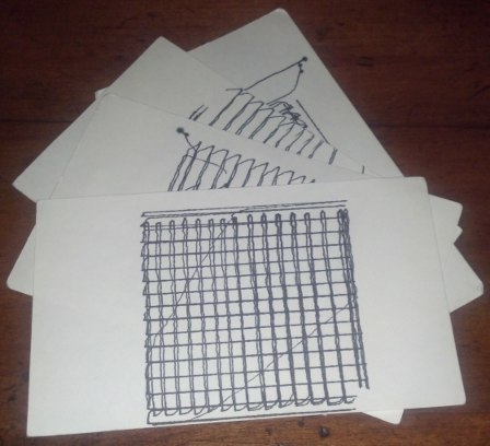
Drawing robot drawings
Since I’m working on designing new parts for my little drawing robot, I’ve decided to list the existing parts for sale on eBay starting at a nickle. I’m not going to print or sell any more copies of this version. One way or another, these parts are gone in less than three days. 🙂
However, before you consider bidding…
However, if you are interested in experimenting with these parts for yourself, you might be able to steal them for a measly $0.05. 🙂 Here’s the link to eBay listing for these plastic parts for a drawing robot.

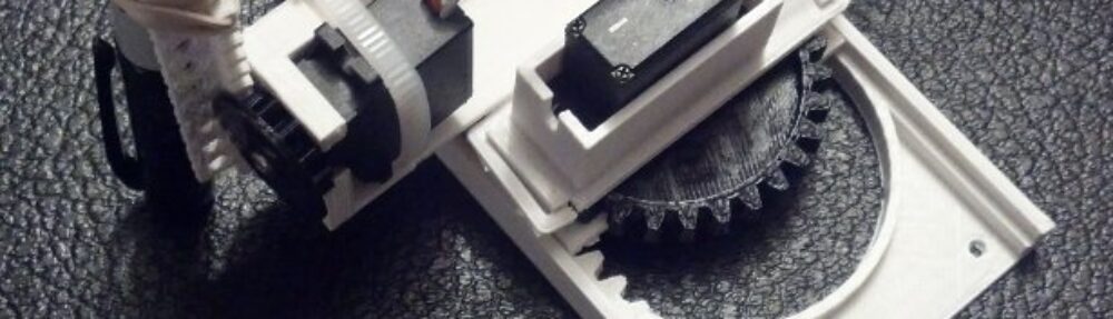
Tiny CNC – all the parts needed
UPDATE: Here’s everything you need to to build a Tiny 3-Axis CNC robot using just 8 plastic pieces.
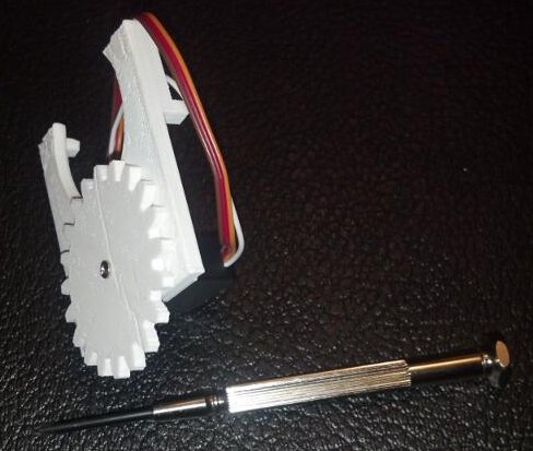
The above are nearly all the tools and parts you’ll need to build your own itty bitty CNC drawing robot. ((You’ll also need an Arduino and some bits of wire)) If you have a 3D printer and a spare Arduino, the rest of the parts should cost you around $20. Right now this robot only has two axes, but in the very near future I hope to add either a Z axis or a pen lift. Without further ado the tools needed are:
You’ll also need an Arduino, some wire to connect your servos to the Arduino, and a USB cable to communicate with the Arduino.
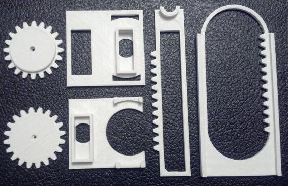
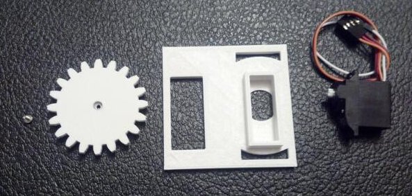
All printed parts
There are only six printed parts necessary for this mini-CNC. If you’re careful, you’ll be able to fit all six on your MakerBot Replicator into a single build plate.
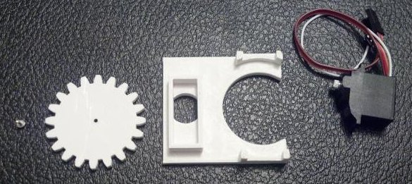
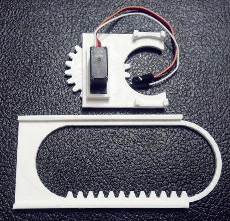
Grab your Micro Servo, the little screw that came with it, the flat gear (really, pinion), and the X axis stage. Just insert the Micro Servo into the X axis stage (it only fits one way), push the gear onto the Micro Servo’s motor shaft, and use the screw to secure the gear. It should look like this when done:
Assembled X axis stage
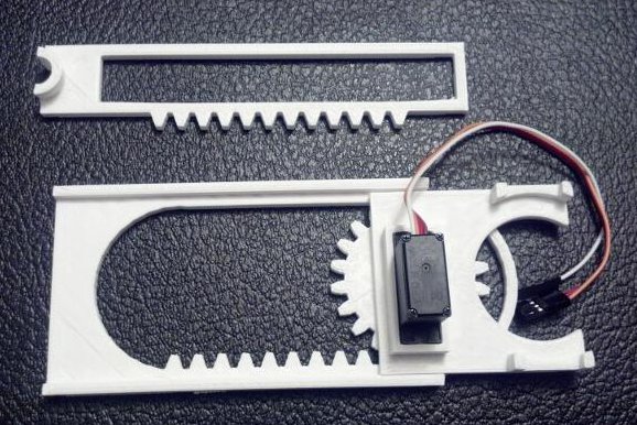
X axis stage and X axis rack
With the X axis stage gear-side down, rotate the gear clockwise until it stops.

X axis stage and X axis rack
Then place the gear into the X axis rack as show.
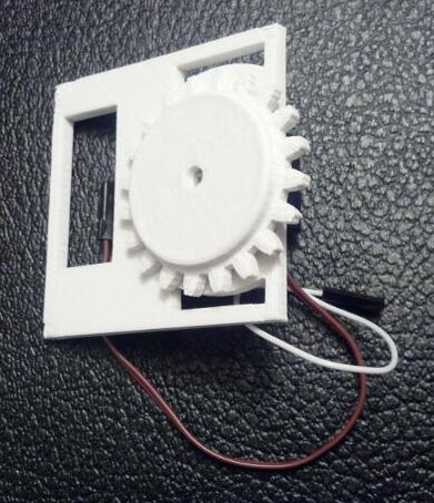
Y axis rack
Locate the Y axis rack and place it over the X axis Servo Motor.
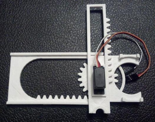
Y axis rack in place
Like so.
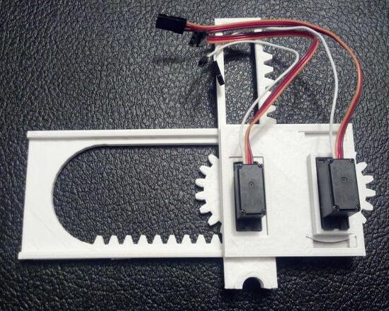
Building the Y axis stage
Just as with the X axis, gather the parts and assemble. This time, the servo motor goes into the stage (it only fits one way), the thick gear is then pushed onto the motor shaft with the gears toward the Y axis stage.
Assembled Y axis stage
Like so.
With the Y axis stage gear-side down, rotate the gear clockwise until it stops.

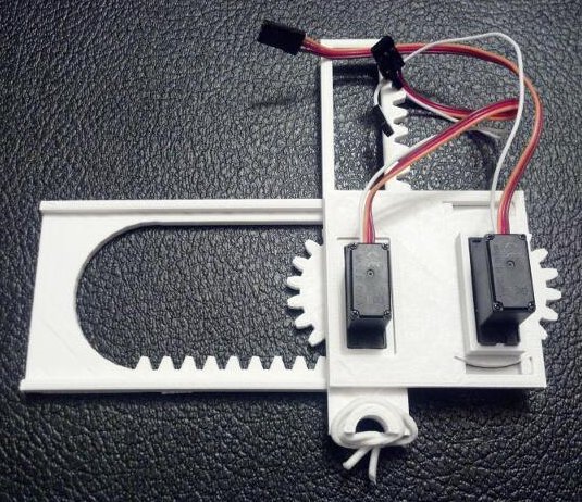
Getting the Y axis stage ready
Route the X axis servo motor wires through the rectangular hole in the Y axis stage.
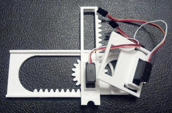
Routing X axis servo motor wires through the Y axis stage
Place the Y axis stage down, with the large rectangular hole around the X axis motor.
Almost done building a robot!
Almost done!
Place the rubber band around the pen holder as shown. You will probably have to wrap it around a few times.
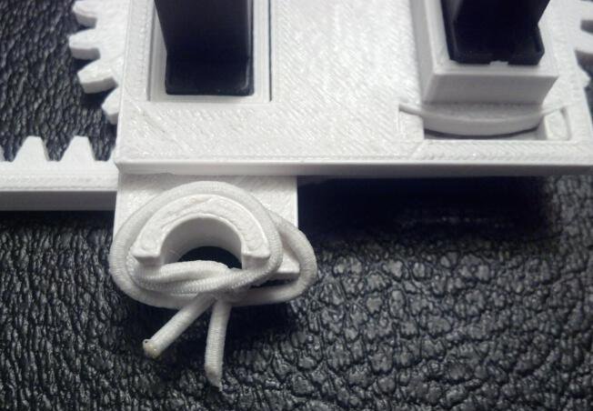
Rubber band wrapped pen holder
Insert a pencil, pointy-bit down, into the pen holder.
Full assembled drawing robot
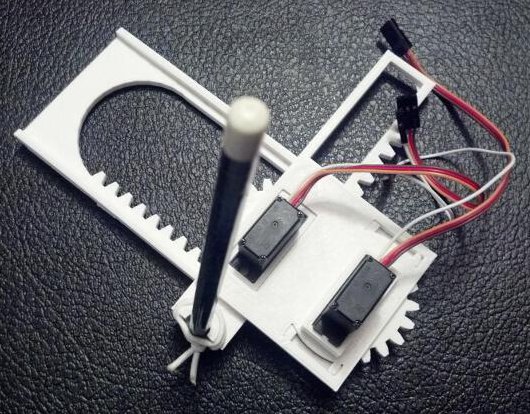
A baby robot is born!
Your robot is done!
To save you a little bit of trouble reading the Arduino sketch and figuring it out, here’s how you would connect your robot to the Arduino:
Download my Arduino sketch to operate this robot. The movements of the robot are hardcoded at the moment, so please check back for updates. Also, if you don’t tape or glue or somehow affix the little bot to a heavy surface, it will literally jerk itself all around the table. (Although, in retrospect, I could have made it draw slower…)
It’s a little difficult to see the lines as the robot is drawing, but it really is drawing a grid in this short video:
I hacked this little project together just in time for the MAKE and GE Robot Hacks presentation on 11/20/2013, so I know there’s lots of room for improvement. Here are some things I’m working on:
I hope you enjoyed this quick to print and easy to use desktop drawing CNC!
Default Series Title
OpenSCAD Rendering of Mini CNC
My daughter and I recently signed up to take part in Make’s Robot Hacks’ project. Make was kind enough to send me a box of parts, including the Make Ultimate Microcontroller Pack and a bunch of servos.
The catch? We had to actually create something and share my progress by November 20. From the time my parts arrived, this was exactly 14 days. 🙂
I had a number of ideas about what I wanted to make – an automated Robo Hand, electronically released spring loaded wings, a little servo-powered walking robot, and a dozen of other smaller ideas. My daughter’s ideas were significantly more ambitious – flying, wall crawling, dancing, hearing, seeing, talking, thinking robots. ((Just put the words on a microchip and put the microchip in the robot’s head, Daddy)) ((Thanks pumpkin!)) The idea that I kept coming back to was a tiny little CNC robot using servos powered by an Arduino – something I had first seen in February of 2012 with Piccolo – the tiny CNC-bot by the Diatom Studio team.
My adventures building robots aside, I still consider myself a “newb.” However, I knew the basics of what I needed to accomplish:
So, for what it’s worth, here’s my process:
Since I had never (!) driven a servo with an Arduino, I needed to figure out how to manipulate at three servos at the same time. Fortunately, the Arduino “Sweep” example explicitly states that it’s capable of controlling eight servos.
Connecting them was significantly simpler than I was anticipating. For the Batan B2122 servos I had, the brown wire was ground, orange wire was positive, and yellow wire was the “control” that would have to be connected to one of the Arduino’s digital out pins. ((If this seems like Greek to you, as it did to me just a few weeks ago, I’d recommend picking up a Mintduino kit and blinking a single LED. You’ll be able to blink two LED’s in no time!)) The easiest way for me to wire up the three servos was through a small breadboard.
Once the servos were wired up, it was a matter of loading up the Sweep example and driving a single servo back and forth. By adding a few lines, I was able to drive two servos, and then three.
The Batan B2122 micro servos are not continuous rotation motors – they only have a 180 degree range of movement. Most CNC machines use stepper motors which are strong, fast, precise, and can rotate continuously forwards or backwards. Servo motors, by contrast, are smaller, cheaper, slower, and unless they are specifically designated as “continuous rotation” have a limited range of movement.
I considered two different ways, each with their own merits, of using a limited range of motion motor to drive an axis of movement. The first way I considered was using a spool and twine to drive each axis – similar to the Printrbot Simple and WaterColorBot. This is an excellent and cheap alternative to using expensive precision toothed belts to control movement. The reason I didn’t use this method is that it would have required a spool for the twine, and some form of rails or metal rods, and of course twine. My concern is that this would have been a bulky solution for such a small robot.
The second method, the one I decided upon, was to use a rack and pinion to turn the rotational motion of the servos into linear motion. One benefit of using a rack and pinion is that the rack itself removes the need for rails or precision rods, spools, and twine – all while providing a sturdy framework for adding additional axes.
As I alluded to above, the micro servos only have 180 degrees of movement. Thus, a gear (or pinion) attached to a servo would only be able to drive the rack by 1/2 of its circumference (or 180 degrees). Keeping that in mind, I chose a gear size that would produce the desired freedom of movement. I settled on a gear radius of about 20mm because it created about 2.5 inches or 62.8mm [ (2 * π * 20)/2 = 62.8 mm] of movement.
Moving a pen over a 2.5″ square would enable me to create nifty little robo-drawn post-its, bespoke business cards, or an auto-signature device.
Here’s what I have so far:
Since the robot isn’t actually capable of doing a whole lot yet, I’ve got a bit to do still:
Since I’m only intending to use this little CNC for small drawings, I don’t really need a huge Z axis lift – even a few millimeters should be sufficient. I was considering cheating a little and just making the “Z axis servo” just lift the front of the robot off the surface.
Even though I’ve got a bit of work ahead of me, I’m pretty happy to have a working proof of concept of a robot of my very own design!
If you would like a little robot like this of your very own, you can find my 3D printable files on Thingiverse and the Arduino code is pretty much the stock “Sweep” example. Stay tuned because I’m looking forward to turning this into a legit itty-bitty CNC drawing robot.
Default Series Title
PlotterBot drawn Calvin & Hobbes on a wagon
The other I came home from work and decided I just had to draw something. ((I feel like when I don’t “make” something for a little while I get kinda twitchy.)) I decided on the above picture of Calvin & Hobbes and set the robot to work. The drawing is big – about 29″ tall and 28″ wide.
While my tallest drawing remains the Yoda, this is definitely the widest drawing I’ve managed thus far. I’m also pleased with my rather simplistic method of centering the robot. ((I’ll be adding a tutorial for this later – it’s a lot simpler than you might think…)) If the centering were off, the remainder of the drawing would be skewed. And, as you can see from the horizontal lines, there isn’t any observable skewing.
There are some very mild artifacts in the drawing – spots where the pen wasn’t lifted far enough off the paper, some areas where you can see how the pen lifted up and down, and places where the shading/hatching doesn’t exactly line up perfectly with the outline of the drawing. Even with these minor issues, I’m really happy with the drawing.