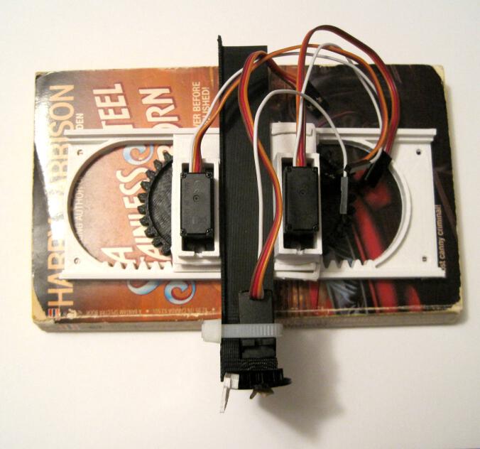
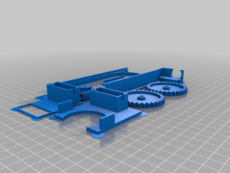
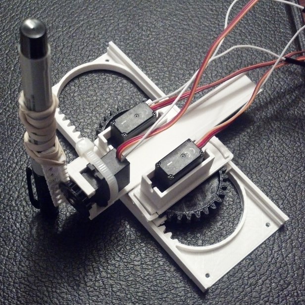
Above is a very short video showing the Tiny 3-Axis CNC, powered by an Adafruit Trinket, using all three axes.
In order to push the Tiny CNC robot design further, I had to actually wire it up and test it. Only by actually trying to put it through its paces am I able to detect design defects for correction/improvement in the next version. What follows are basically my notes working with the Trinket and thoughts on the design of the robot thus far. It helps me to document such notes for future reference – so you may or may not find this stuff interesting. 🙂
- Adafruit Trinket
- While I’ve wired the Tiny CNC to an Arduino Uno and a Mintduino before, I really wanted to get it to work with my Adafruit Trinket (courtesy of Adafruit and Hackaday!). I figured this was as goo a time as any, so I soldered the headers onto the Trinket and got started on the process of augmenting my Arduino IDE to work with it.
- The Adafruit Learning System website has an entire section introducing the Trinket. The process is well documented, but still a bit fiddly. It’s not nearly as “plug and play” as working with an Arduino Uno. However, this is a perfectly acceptable tradeoff for the size and price of the device. If you want a “quick start” guide to getting the Trinket to work with your Windows system, this a rough outline of my process:
- Download the Trinket drivers. The notes for different operating systems is helpful here.
- Add ATtiny85 support to your Arduino IDE. This is for the “slow” way of augmenting your existing Arduino IDE. I prefer doing this to having multiple versions of the Arduino IDE on my system.
- Rename and replace the avrdude.conf file in the “hardware\tools\avr\etc” folder.
- Rename and replace the avr-Id.exe file in the “hardware\tools\avr\bin” folder.
- In an ideal world, I’ll be able to use the Trinket to both control three servo motors and speak to the fake serial port so it I can send instructions from the computer. However, due to the limitations1 of the Trinket, the way it handles servos and serial communications are a bit hacky.
- Trinket servo motor control. Servo motor control apparently requires the microcontroller utilize an internal timer/clock. However, since the Trinket sacrifices this for size/space reasons, a work around using an internal clock/timer has to be implemented. The result is that you have to use a different servo motor controller library that implements the software clock/timer. The trick is that the timer has to be refreshed every 20 ms or so to operate the servo. Using a simplified version of the Adafruit Trinket servo motor control sketch, I was able to get the Trinket to move all three axes.
- Trinket serial port communication. Again, the Trinket sacrifices serial port communications in favor of size/space requirements.2 Fortunately, there appears to be a work-around for this limitation using a “fake USB serial” connection. I haven’t finished this process and don’t have much to say about it at the moment.
- Tiny CNC Arduino (not Trinket) Sketch
- Using Oliv4945’s Arduino Gcode interpreter for Mini-CNC as a starting point, I wrote a sketch for making the Tiny CNC respond over the USB serial connection to WSAD (forward, back, left, right) and OL (up, down) commands. The good thing about this sketch is that you can give the ‘bot a series of commands, hit Enter, and have it carry the instructions out.
- Tiny CNC Trinket Sketch
- This sketch is a simplified version of the Adafruit Trinket servo control sketch. The XY servos move over about 30-40 degrees while the Z axis pumps up and down. This is what you see happening in the video above.
- MORE Tiny CNC Design Thoughts
- Overall, I’m very happy with version 0.29. The bottom line is that it works. As Michael Curry recently pointed out, “at this point you have something that works, so the rest is just corrections.” If you build this version on your own, you’ll get a little robot that is a bit finicky – but will actually be a no foolin’ tiny 3-axis CNC. It won’t be super precise or able to handle a router or mill attachment, but it also won’t cost $400 for a kit. 🙂
- Here’s What Worked
- Z axis. My first attempt at printing a Z axis works. The Z rack isn’t much more than a thin plank of plastic with a rack of teeth and some holes to help mount a pen or whatever to it – but, again, it works.
- Y rack and Y stage/motor mount. The parts in this little robot are designed to fit/slot/snap together and lock themselves and each other into place. I’m really really happy with how this designed worked out. I basically entirely changed the entire method of securing the Y rack from version 0.18 to version 0.29. In version 0.18 the Y rack slid along each side of the X motor mount. In this version, it rides between the X and Y mounts, held in place by the Y pinion (gear), riding over the Y stage motor mount, and constrained by the X and Y motor mounts. While not actually simple to accomplish, I feel like this was an elegant solution. While I have some improvements planned for the next version, I don’t anticipate this changing at all.
- Rubber band gaskets. The problem with using printed pinions (gears) instead of the servo horns that come with the servos is that they don’t have the itty itty splines to mesh closely with the grooves on the servo motor gear. As a result, no matter how hard you tighten down the servo motor set screw, the gear can twist away. My method of dealing with this was to cut a small piece out of wide rubber band to use as a “gasket” between the set screw and the gear. As you tighten down the set screw, it puts pressure on the rubber band and gear. When the gear moves, the rubber band gasket prevents the set screw from rotating/sliding and loosening with use.
- Zip tie. The zip tie on the Z motor seems to work very well. I used a similar system for holding the servo in my PlotterBot pen holder. The motor is held in place securely without much room for wiggling. Although it is definitely possible to create a printable Z motor holder that doesn’t require any zip tie, the version I designed doesn’t require any overhangs. I’m trying to avoid overhangs and support requirements in parts (which rules out all kinds of nifty groove/slide systems) so make everything easier to print and possibly easier for injection molding.
- Twist tie. While not part of the directions or other documentation so far, I found a twist tie very helpful in controlling the sevo motor wires by bundling them together.
- Thinning and hollowing the XY pinions. Since the most recent published version I made these big pinions slightly thinner and hollowed them out a little. This theoretically reduces plastic a little. Indeed, the 3-axis version of the robot actually uses less plastic than the 2-axis version I had uploaded a few weeks earlier.
- Here’s What Didn’t Work/Could Be Improved
- Rubber band gaskets. These gaskets provide a drastic improvement for the gear’s ability to stay properly tightened on the servo shafts. However, they’re not ideal since the rubber band gaskets just serve to create a little extra friction/traction between the set screw and the pinion (gear). Now I’m trying something new that seems to work even better. My daughter has these adhesive foam stickers in the shape of letters and animals. For shapes with cutouts (like the letter “O”) the inside of the cutout is useless to her and is either found floating around the bottom of the bag or still slightly attached.3 I’ve place one of these between each of the set screws and pinions (gears). The benefit of these is that they actually adhere to the surface of the pinion and actively resist being turned against the pinion. Another benefit of these is that they are thicker than a rubber band, so the set screw has to sink into them – creating more surface area contact between the “gasket” and the set screw.
- Y rack/Z motor mount. I found that the zip tie for the Z mount interferes slightly with the Y rack slide. I’ll need to raise the Z motor mount slightly to compensate. Plus, I only just now realized there’s a slight overhang in this part I would like to eliminate.
- Z pinion. The Z pinion includes a little flange to keep the Z rack in place. The flange is a little too large and needs to be reduced slightly for easier operation.
- Z rack. The Z rack isn’t much of anything, as mentioned above. It’s just a rack with a plank with holes in it. It could be better refined to work as a pen holder without a lot of design work. I just banged this one out so that I could have an actual no foolin’ 3 axis CNC to work with. I have some ideas on how to make a simple pen holder. Ideally, I would have two separate Z racks for this robot – one for holding a pen and another for use as an actual 3 axis CNC.
- Carriage tipping. When the XYZ carriage has the Y rack extended as far out a possible, the weight of the extended Y rack with the Z motor and pen are more than enough to cause the entire XYZ carriage to tip out of the X rack. This could be fixed by just creating a little guide, applying a piece of wire, or any number of minor hacks. However, I’d like to have this issue resolved as part of the design of the robot. Thus, I’m thinking of inverting the entire X rack to cause the X pinion to lock the X gear in place against the X motor mount. The problem with this method is that it will basically require redesigning the X and Y pinions again.
- Anticipated Hardware Changes. If I implement the improvements and changes I’m contemplating, this would mean redesigning the X rack (to invert it), X and Y pinions (to work with newly inverted X rack), Z pinion (to reduce the flange size), Z rack (to include a better pen holder). Y rack/Z motor mount (so the Z motor zip tie doesn’t hit the X motor mount), possibly Y motor mounts (to thicken the base slightly), and possibly the X motor mount to reduce plastic usage (since it wouldn’t have to be as big any more). And… that’s a change to all 8 pieces. :/
- Anticipated Software Changes. Trinket space permitting, I would like to incorporate a small Gcode interpreter and fake USB serial connection. I don’t know if this is possible, but I’d like to do this. Also, my daughter specifically requested a 6-button interface to operate the robot. I don’t know how to do this yet – but I’m willing to learn. 🙂 With three pins on the Trinket used for the three motors, there are only two pins left for buttons. I’m pretty sure there’s no way to hook up a set of 5+ buttons to a Trinket and still have it operate all three motors.
- Fanciful Potential Changes.
- Keypad. If this robot were to be powered by an Arduino Uno, you could probably incorporate this awesome 10-digit keypad from Adafruit to control the robot. I think that would be a fun and accessible way for a kid to interact with this robot.
- Robotic Gripper. With a fourth servo, a small robotic gripper hand could be attached to the Z axis – allowing this robot to do all kinds of interesting things. It could be used to play chess, sort marbles, flip switches, or pick peas out of your dinner.


